Custom High-Performance E-bike
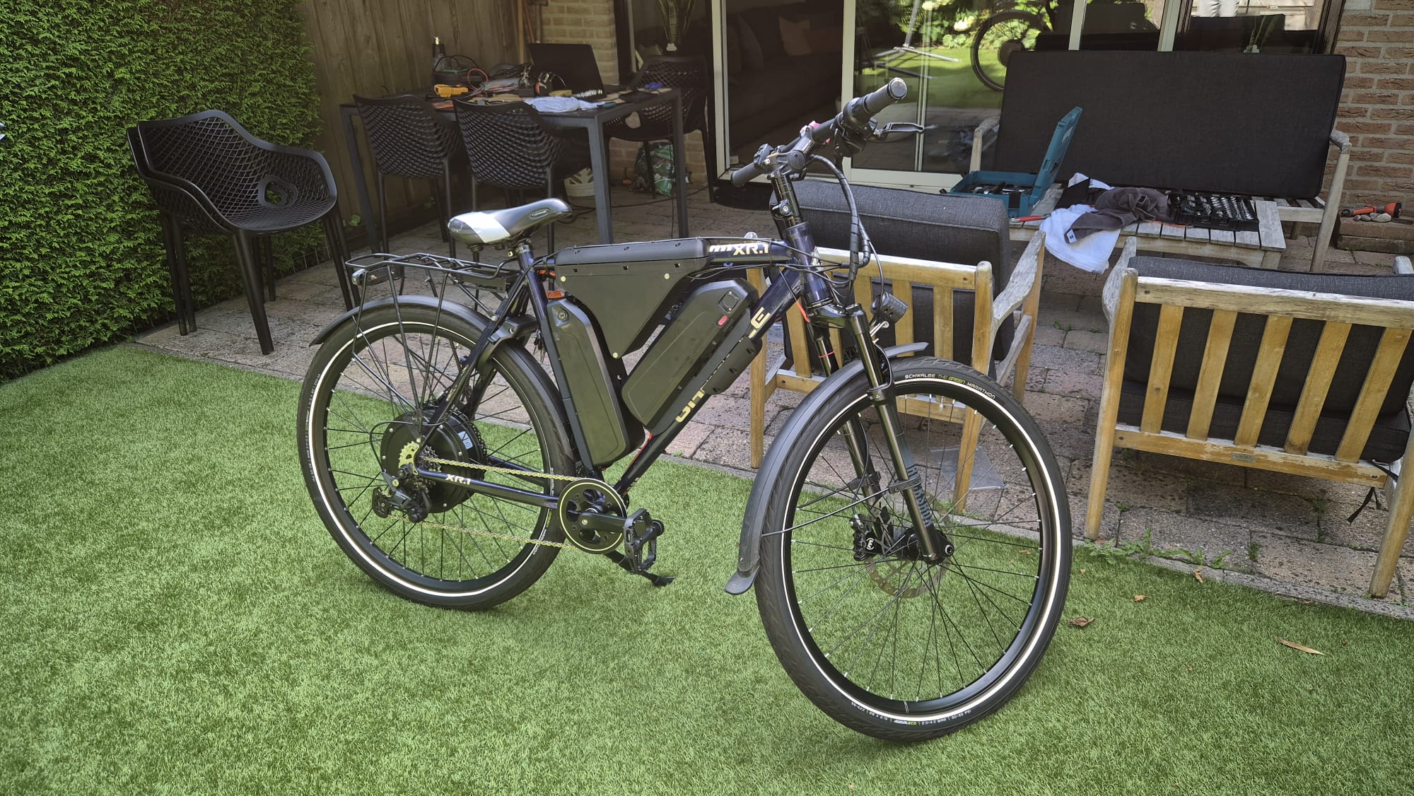
A seemingly never-ending project in which I design, develop, and program my own custom high-performance E-bike based on the open-source VESC project.
Backstory
I have always been interested in bicycles, even as a young child. I was constantly working on my bike, although at the time this mostly consisted of loosening bolts and tightening them again.
In 2021, I started studying Applied Sciences at TU Delft and needed a bicycle to get around Delft. I received an old bicycle from an uncle through my aunt. Applied Sciences turned out not to be the right fit for me, so I stopped and took a gap year, leaving me with an extra bicycle sitting in the garage.
Setup 1 - The first step
During that gap year, my younger brother wanted to build an E-bike. We built his using a generic E-bike conversion kit and three car batteries connected in series, which was admittedly a rather unusual choice. These were later replaced with a normal lithium-ion downtube battery.
I wanted to build an E-bike myself as well, but I wanted to approach it more seriously from the start. I used the bicycle I still had available and ordered a 750 W conversion kit from AliExpress. I bought a 48 V downtube battery and mounted it using custom resin-printed mounting brackets. This did require drilling holes into the bicycle frame.
I completely refurbished the bicycle and installed all of the electronics. The result was a clean, retro-looking E-bike.
This first setup introduced me to how a conventional E-bike system works and to the wide range of components and solutions that were available online.
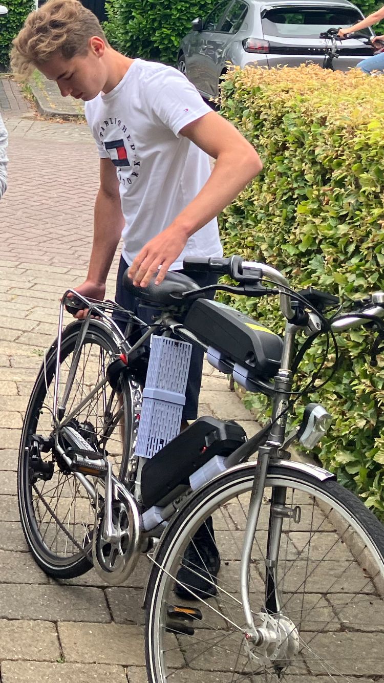
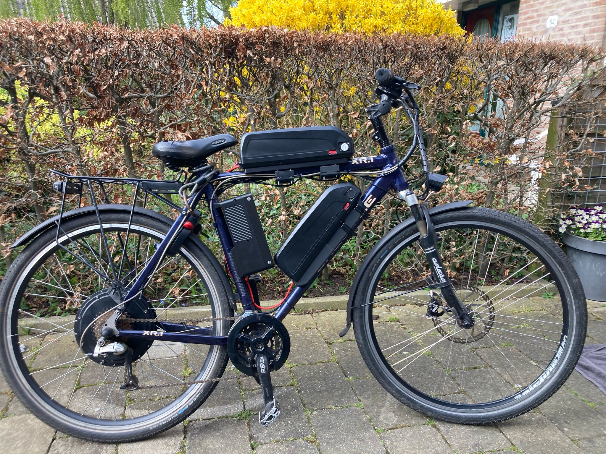
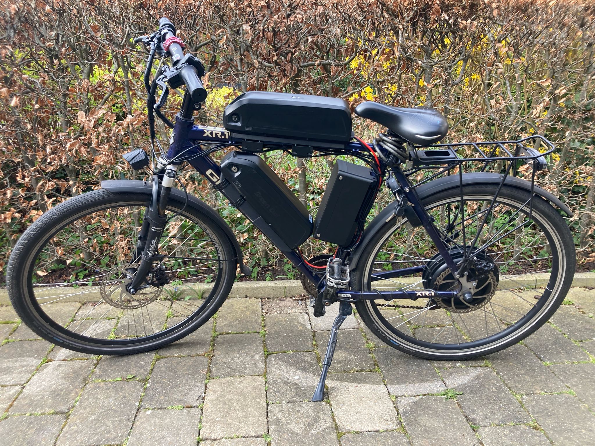
Photo setup 1
Setup 2 - Increased power
After enjoying the original E-bike for quite some time, I wanted to get more performance out of it. After a lot of searching, I found a 90 V, 50 A controller that was compatible with the original display.
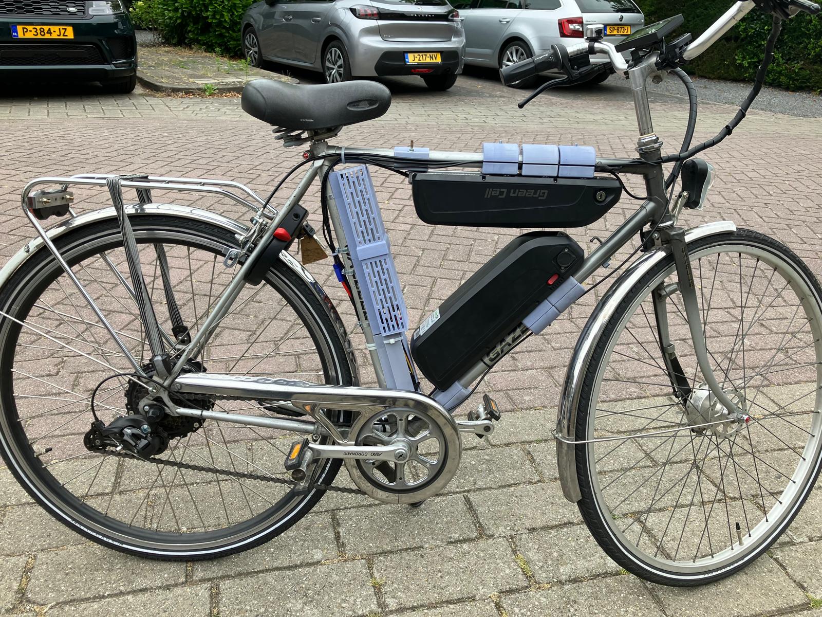
I added a 36 V battery in series with the existing 48 V battery, creating an 84 V system. Because both battery packs retained their own BMS, I added a reverse-connected protection diode across each battery pack. If one BMS disconnected its battery during a protection event, the diode provided an alternative path for the series current and protected the disconnected BMS from being exposed to a potentially damaging reverse voltage. I also made new high-current cables using crimp connectors.
This was where I encountered my first major limitation. Standard E-bike batteries typically use a BMS that does not allow much more than approximately 35 A, while the controller attempted to draw 50 A. This caused the batteries to shut down whenever I applied too much throttle. My first solution was simply not to use too much throttle. After searching online, I discovered that my specific display and controller combination had a configurable battery current limit. After changing this setting, the problem was resolved.
Setup 3 - Improved reliability (and even more power)
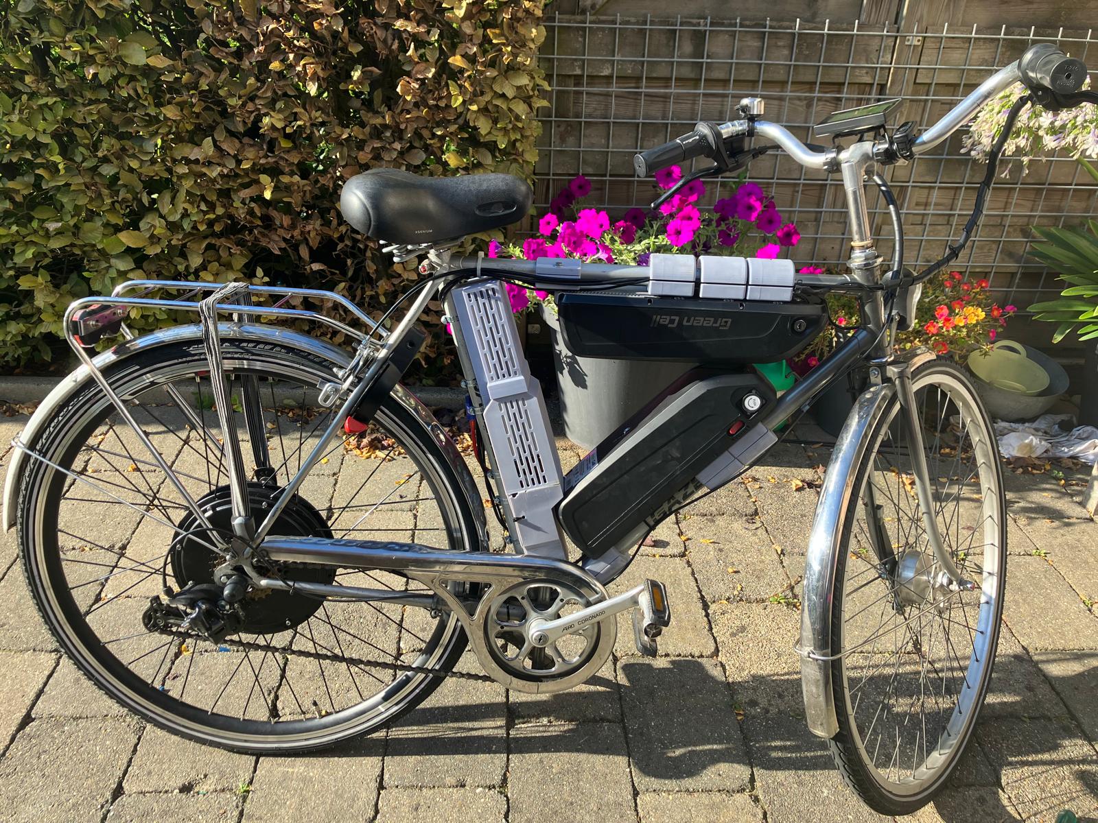
In Setup 2, I was pushing approximately 3000 W through a motor that was originally rated for 750 W. Eventually, Joule’s law caught up with me and the geared hub motor became so hot that it was close to becoming electronic waste.
I concluded that a 1000 W-rated direct-drive hub motor would be a much better solution. In practice, this turned out to be correct.
Around the same time, the crimp connectors started vibrating loose. At that point, I decided I really needed to learn how to solder. I soldered all of the connectors permanently and never experienced vibration-related connector failures again.
I did not realize it at the time, but learning to solder opened up an entirely new range of possibilities for later projects.
Setup 4 - New frame
The electronics were now functioning well, but the additional batteries and heavier motor had significantly increased the overall mass of the bicycle. I therefore wanted to move to a stronger and higher-quality frame.
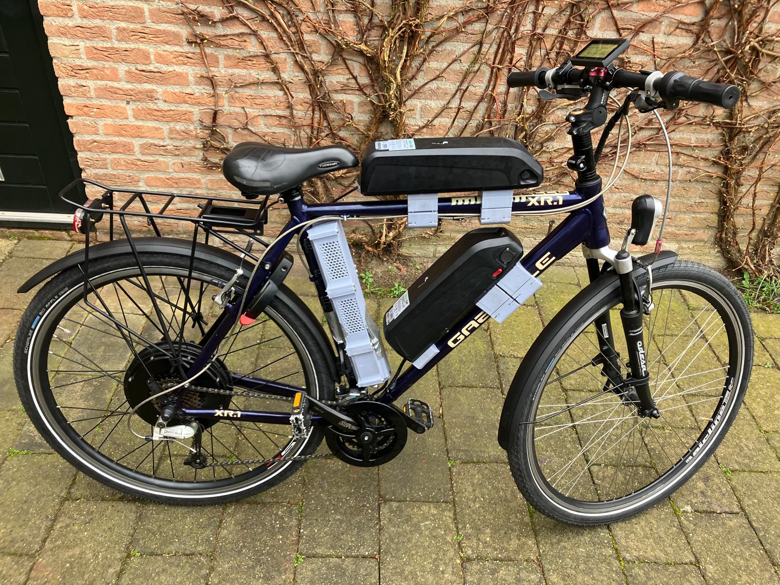
My father had always owned a cross-country mountain bike that he took very good care of, a midnight-purple Gazelle XR1. As a joke, I searched for the same model on Marktplaats and found one in relatively poor condition for only €60. We picked it up the following evening. A lot of work was required to restore the bicycle, but the most important component, the frame itself, was still in good condition.
The frame swap turned out to be more difficult than expected. The previous bicycle used simple round frame tubes, while the Gazelle XR1 used custom-shaped tubing. At this point, my CAD skills were still relatively basic. However, mounting the batteries properly on the new frame forced me to learn CAD in much more depth. This stage of the project effectively marked the beginning of my more advanced CAD work.
After many hours in SOLIDWORKS and several test prints, I had approximated the frame tube geometry accurately enough to design custom battery mounts. These allowed me to securely mount the batteries without drilling additional holes into the frame, using the existing bottle-cage mounting points to attach custom 3D-printed battery mounts. For this setup, I also researched battery management systems in more detail. I replaced the original BMS units with higher-current models so that the battery packs could safely deliver the full 50 A required by the controller.
Setup 5 - VESC (more power)
The upgraded controller I was still using relied on square-wave motor control, which made the motor extremely loud and also generated more heat than I wanted. I wanted something significantly quieter. After researching alternative control methods, I discovered Field-Oriented Control. The most practical way to implement FOC in a compact system was through the open-source VESC platform.
MKSESC 75100
I started with a Makerbase MKSESC 75100. This controller could potentially increase the system power from approximately 4000 W to around 5000 W while also providing almost silent motor operation.
For this setup, nearly all wiring had to be custom-made and soldered. This included soldering very thick high-current cables, which was considerably more demanding than the smaller electrical work I had done previously. Unfortunately, I could no longer run the complete 84 V battery configuration because it exceeded the voltage range of the controller. I therefore temporarily returned to using only the 48 V battery. I also had to learn how to configure the VESC platform. Nearly everything had to be set manually and the motor parameters needed to be properly tuned.
Because I forgot to disable flux weakening and had not tuned the motor parameters properly, I eventually managed to destroy both a controller and a motor.
MKSESC 75200
When something breaks, it is obviously time for an upgrade.
I replaced the damaged controller with an MKSESC 75200. This controller approximately doubled the available power capability and had a significantly better electrical design.
I also purchased a new 2000 W hub motor.
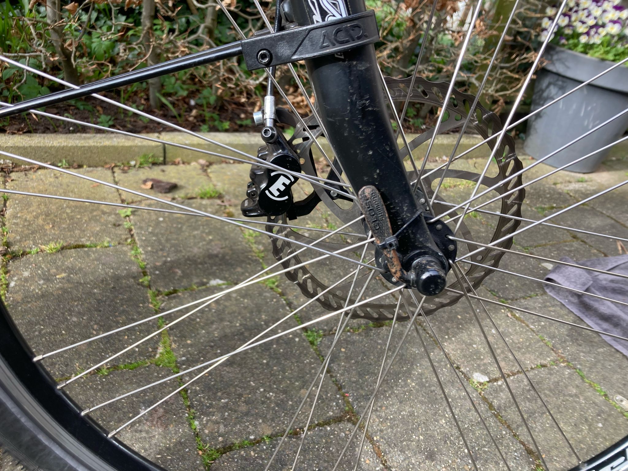
After increasing the drivetrain performance, I decided it was also time to upgrade the brakes. I installed Magura MT5 brake calipers, ceramic brake pads, and 203 mm brake rotors.
This configuration remained reliable for a long period of time.
Custom batteries
To unlock the full potential of the upgraded drivetrain, I needed different battery packs.
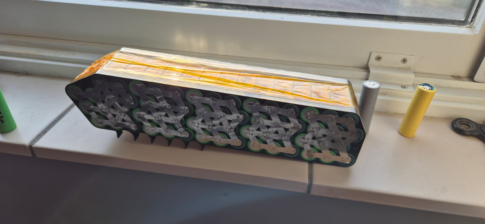
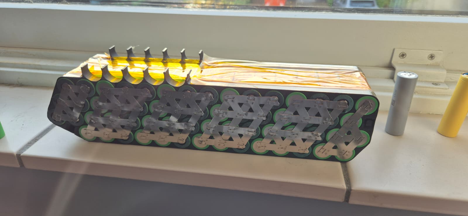
The goal was to create batteries capable of delivering approximately 150 A while remaining within the dimensions of conventional downtube E-bike batteries and providing approximately 72 V in total. Consumer battery packs with these specifications were not available, so I decided to build them myself. After extensive research, I settled on two custom downtube batteries. Each battery used a 10S6P configuration with Sony Murata VTC6 cells rated for approximately 30 A continuous discharge.
The packs used 180 A BMS units and a double layer of 0.2 mm spot-welded nickel strip to connect the cells and parallel groups throughout each battery pack. Building the packs required me to learn how to spot weld, so I bought a small spot welder from AliExpress and used it to assemble the cell connections.
I purchased 130 cells for the project. I tested the capacity of every individual cell and selected the best 120 cells for the final battery packs. I then used rePackr to create balanced parallel groups with closely matched capacities.
I reused the same type of downtube battery housing that I had used in the earlier setups. This saved a considerable amount of enclosure design work and allowed the new high-current packs to retain the compact form factor and mounting style of a conventional E-bike battery. I designed custom internal cell holders for the housings and soldered the BMS wiring into place. These new batteries unlocked significantly more power while also increasing the available range.
The complete battery system now had an energy capacity of approximately 1340 Wh, a nominal voltage of 72 V, and a maximum continuous current rating of over 150 A.
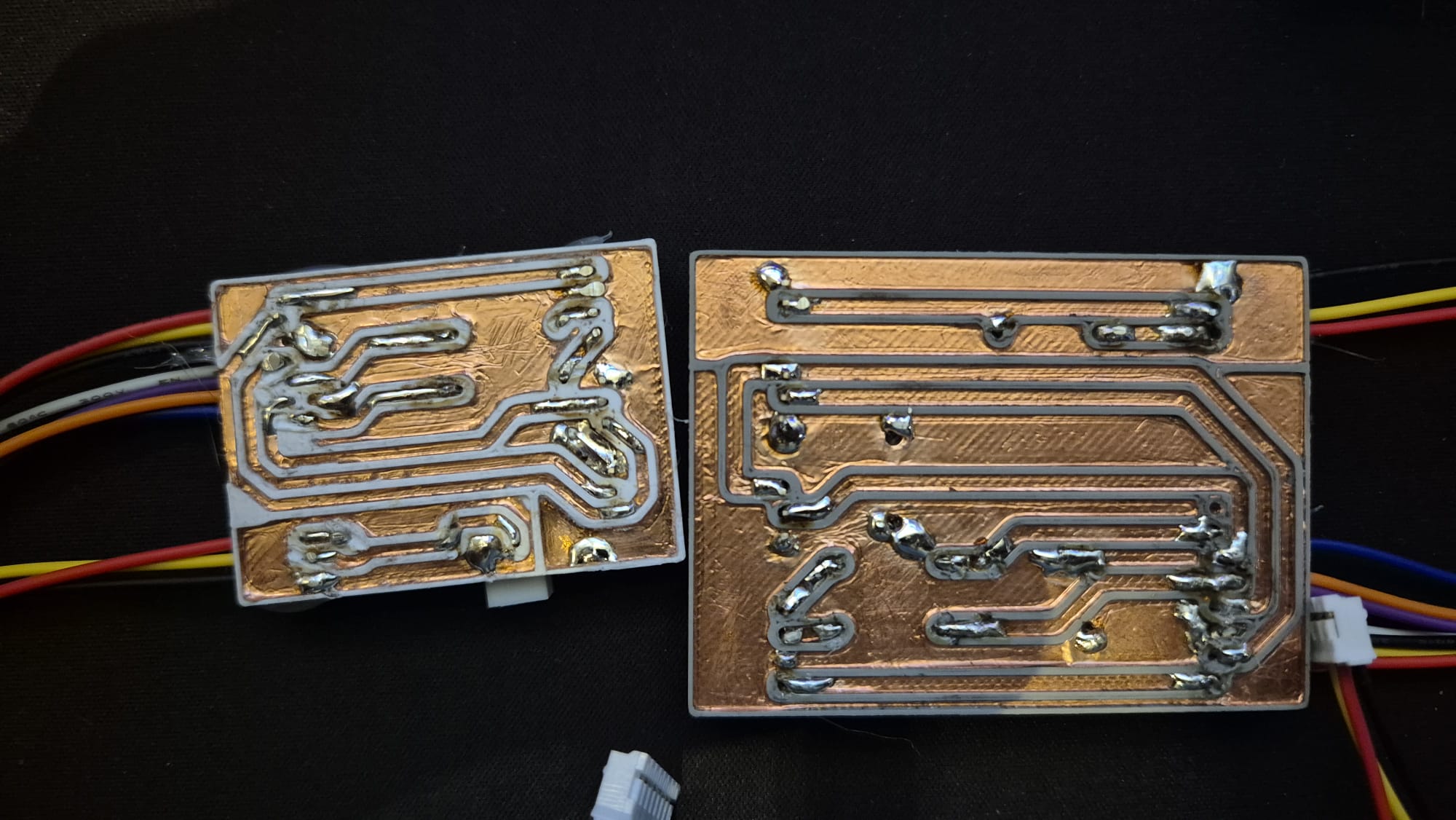
3D-printed PCB
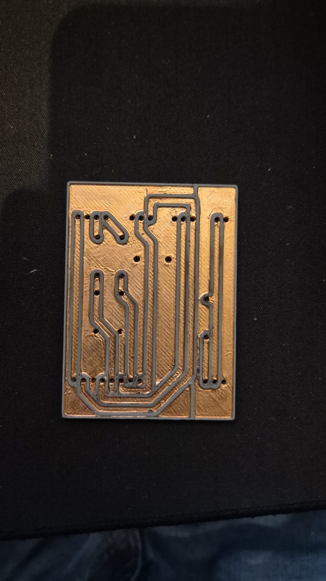
As the wiring became increasingly complicated and several 3.3 V and 5 V signal conversions were required, I developed a method for producing simple PCBs using a 3D printer.
First, I designed the circuit in KiCad. I kept approximately twice the nozzle width between the traces and the ground plane.
I then exported the PCB as a STEP file and imported it into Onshape. The gaps between the traces and the ground plane were extruded upwards and the holes for through-hole components were enlarged to compensate for the limitations of FDM printing.
The PCB substrate was then 3D printed.
I covered the complete surface with copper foil and pressed it firmly onto the printed structure. Because the spaces between the traces and the ground plane were raised, I could easily sand the copper away from these areas. This left copper only where the conductive traces were located.
The through-hole components were then inserted and soldered directly onto the remaining copper foil.
Dropout Reinforcement and Torque Management
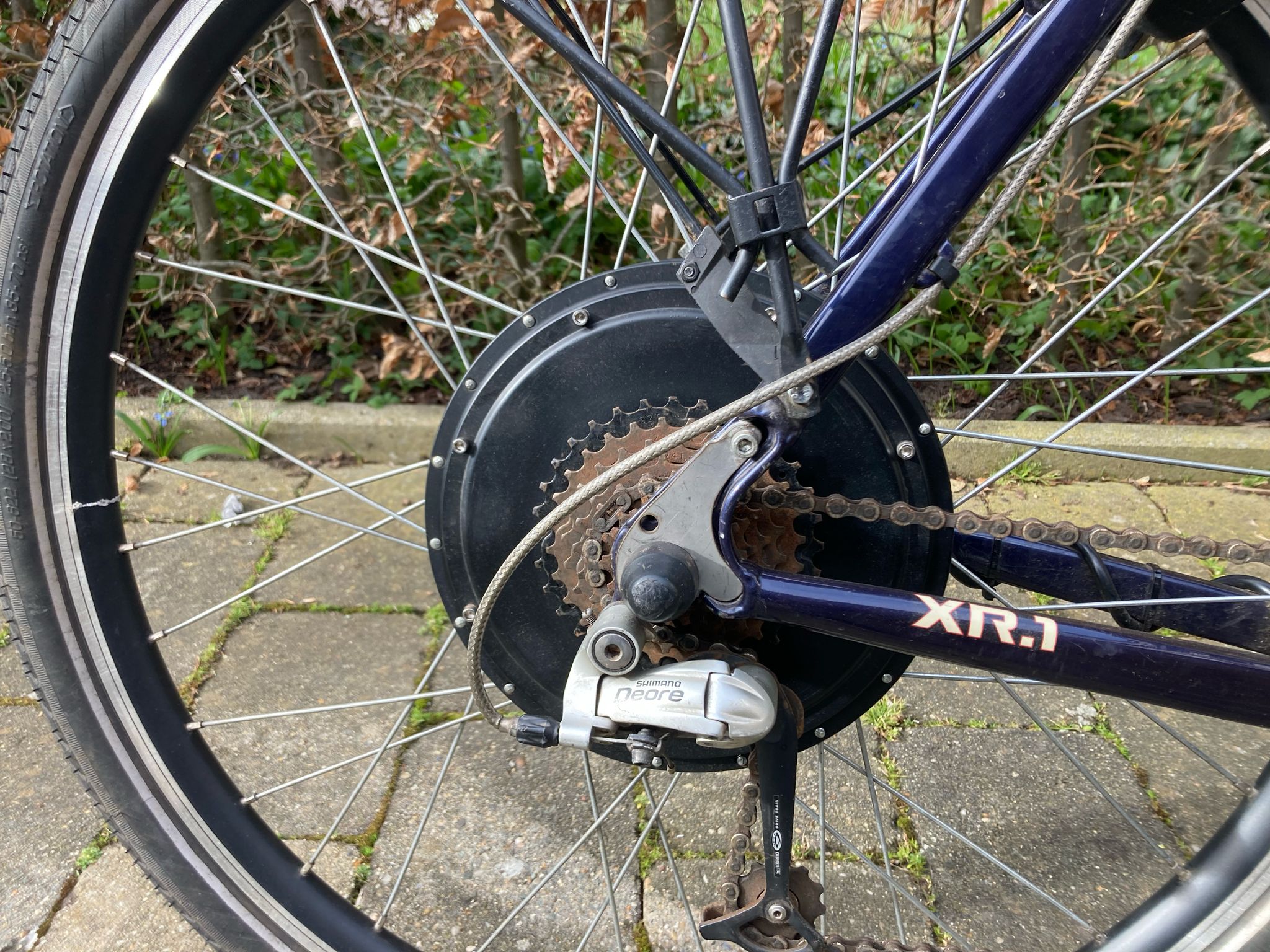
For the 75200 controller version, the torque acting on the rear dropouts became so high that the motor axle started to pry the dropouts open. As a result, the motor effectively tried to rotate underneath the bicycle frame.
To prevent this, I remodelled the rear dropout geometry based on a well-aligned perpendicular reference photo. I then designed custom stainless-steel plates that fitted around the motor axle and locked into the rear dropouts in a form-fitting way. These plates were clamped in place by the motor axle nuts.
Axle rotation was prevented in two ways. First, the plates matched the dropout geometry closely, creating a strong geometric constraint. Second, the plates were additionally secured using bolts that aligned with the original disc brake mounts on one side and an existing hole in the dropout on the other side.
The correct geometry was first developed through a trial-and-error process using 3D-printed prototypes. Once the design had been validated, I had multiple 2 mm stainless-steel plates cut and stacked three plates per side to create the final reinforced dropout interface.
Sensorless FOC limitations
There was still one major issue. In my setup, the direct-drive hub motor proved difficult to control reliably using sensorless FOC at low speed and high motor current. As a result, the motor had to run using Hall sensors at low to medium speeds. Hall sensor interpolation still provides FOC-like behaviour, but it was not the level of control I was aiming for. I wanted the system to operate as accurately as possible.
MKSESC 84200HP
The MKSESC 84200HP introduced phase-line sampling and improved current amplifiers, allowing the controller to measure the motor currents more accurately. More accurate measurements resulted in improved motor control.
With the MKSESC 84200HP, packaging the electronics and batteries became more difficult because the controller and supporting hardware occupied more space. The downtube batteries normally slide onto dedicated base plates that also provide the locking interface. To gain as much clearance as possible, I reverse engineered these battery base plates and integrated the required mounting grooves directly into my custom 3D-printed parts. This eliminated the need for an additional separate mounting plate and reduced the installed battery height by approximately 4 mm. That small reduction in height was important because the available packaging space around the batteries and electronics had become extremely limited. I later made these reverse-engineered base plate designs available on my Cults3D page in STEP format for a small price. The idea was to provide other E-bike builders facing similar packaging constraints with a CAD-ready starting point that they could directly integrate into their own custom battery mounts.
Sensorless FOC became almost perfect. The only remaining issue occurred during the transition from sensored to sensorless FOC at very high motor currents of approximately 250 A.
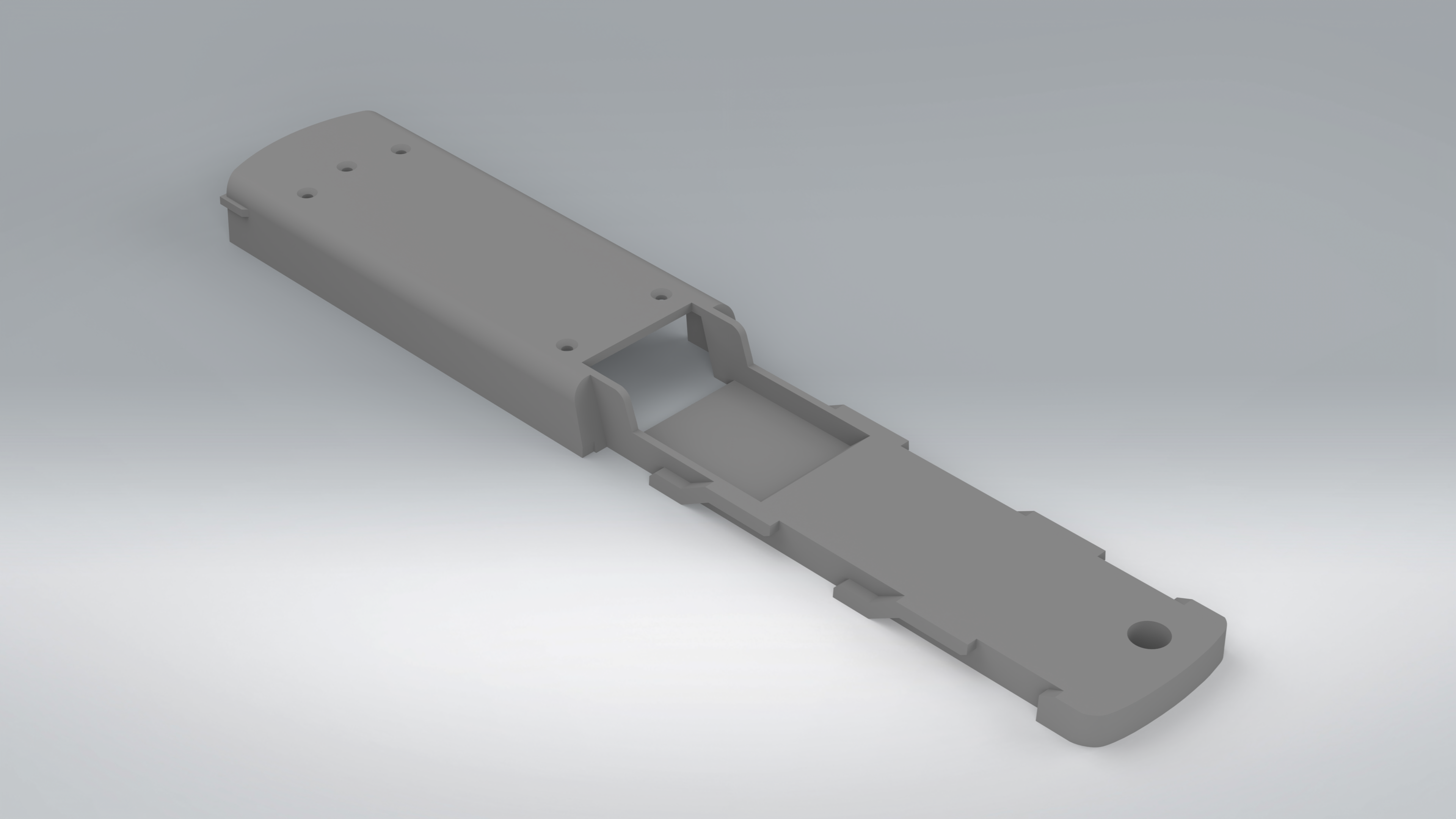
Hailong 1-2 Downtube Base Plate
Reverse-engineered base plate for the larger 65-cell Hailong 1-2 downtube battery case, supplied as a STEP file so it can be integrated directly into custom E-bike battery mounts.
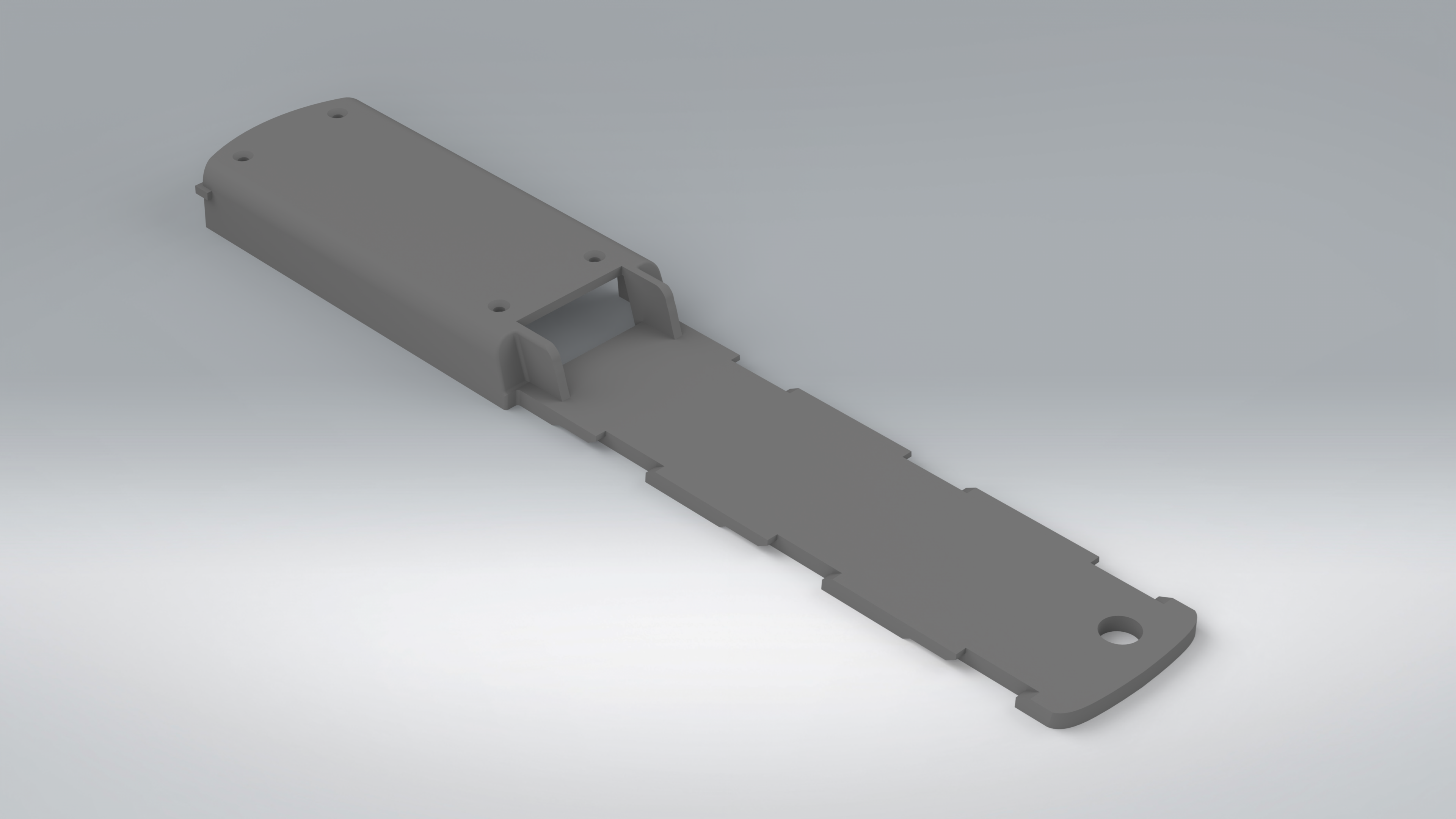
Hailong 1 Downtube Base Plate
Reverse-engineered base plate for the 52-cell Hailong 1 downtube battery case, designed as a CAD-ready STEP model for integration into custom mounting solutions.
Setup 6 - Hardware changes + RMCore
The 2000 W hub motor used a relatively low winding count. This meant that it required very high motor current to generate torque and was optimized for a top speed much higher than I realistically needed. I rarely rode at very high speeds. What I actually wanted was strong acceleration.
Drivetrain and chassis upgrades
The logical solution was therefore a larger motor with a higher winding count. I custom-ordered a 3000 W hub motor from China with a winding optimized for lower speed and higher torque, capable of approximately 280 Nm.
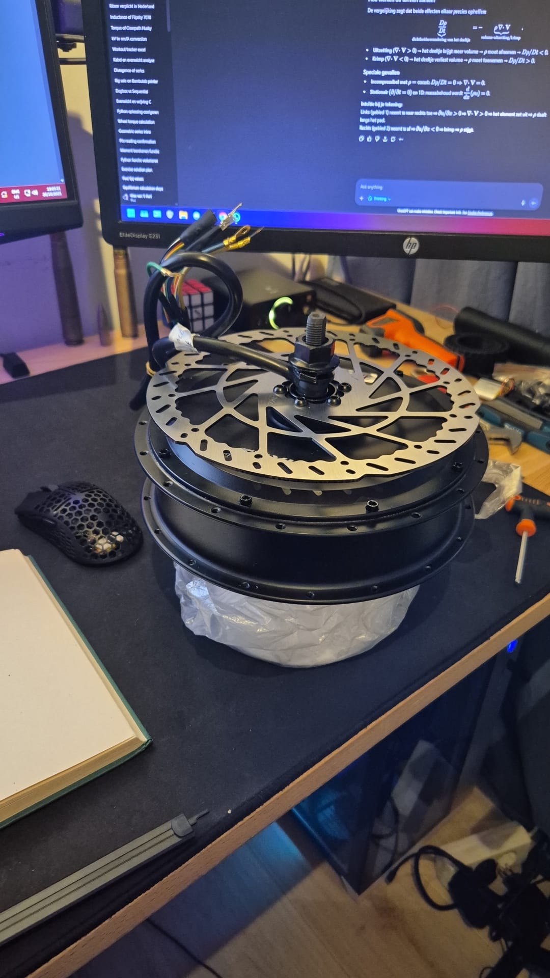
I purchased stronger spokes and a higher-quality rim separately. I then laced the custom-ordered 3000w hub motor into the wheel myself using a double-cross spoke pattern. The stronger spokes and improved rim increased the mechanical safety margin of the rear wheel. The higher motor torque also introduced additional mechanical risks, so I needed to further reinforce the rear dropouts. For this version, I 3D-scanned the rear dropouts with the motor mounted in the frame and used this scan data to design a new set of plates with a much more accurate fit. These final torque plates were manufactured from 6 mm stainless steel and provided a significantly stronger and more precise solution for handling the increased motor torque.
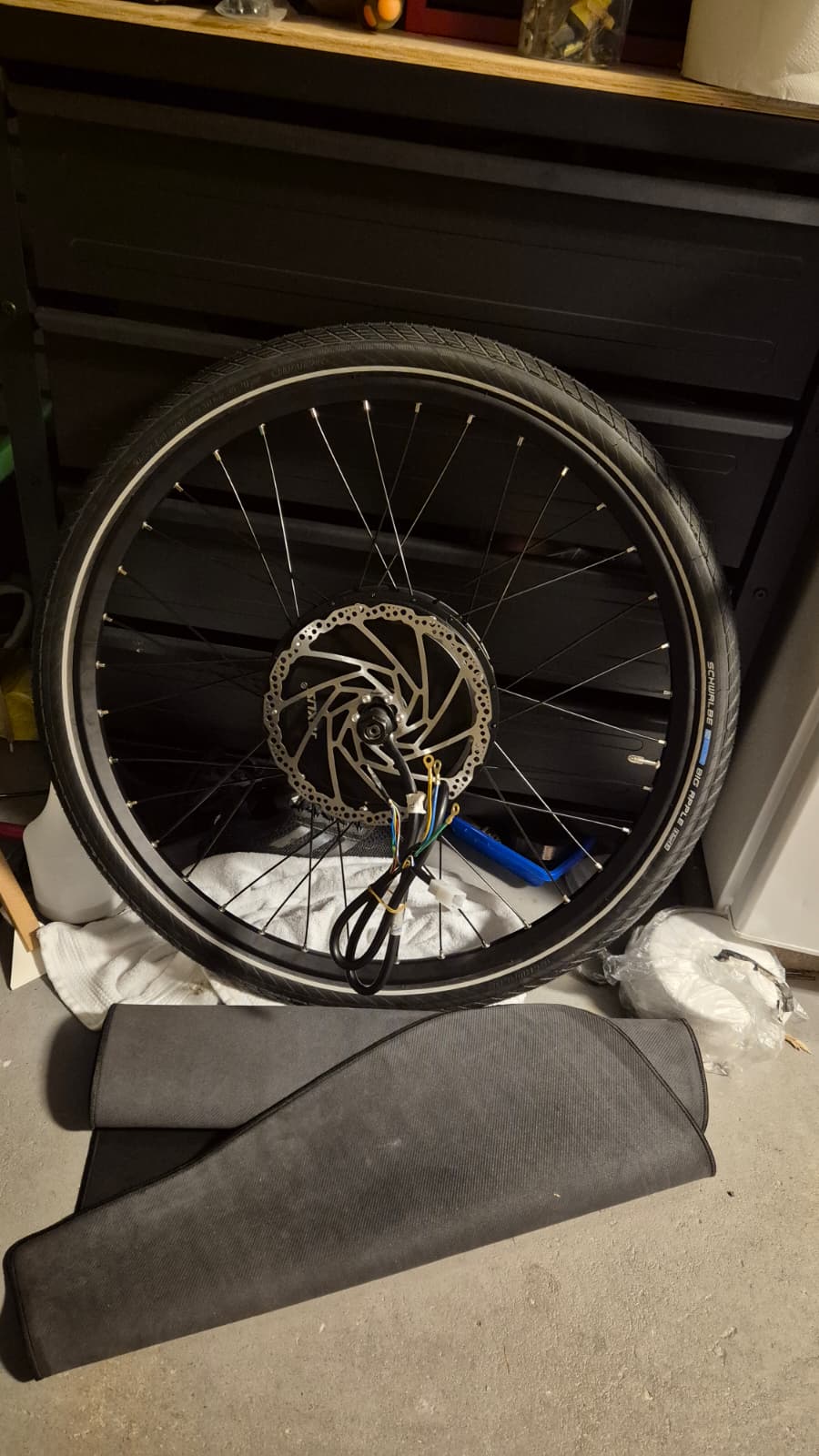
I also replaced the headset so that the frame could accept a modern tapered front fork instead of the original straight-steerer design. The new air-sprung fork increased the wheelbase, reduced the tendency of the bicycle to pitch forward under hard braking, improved front-end stiffness, and replaced the original quick-release wheel connection with a 15 × 110 mm Boost thru-axle. To match the new fork, I replaced the front wheel with an eMTB wheel built around the 15 × 110 mm Boost standard and using a triple-cross spoke pattern.
The braking system was upgraded again. I retained the Magura MT5 calipers, but increased the rotor size to 220 mm at the front and 225 mm at the rear. The 225 mm rear rotor was chosen partly to create sufficient clearance between the relatively thick MT5 caliper body and the side plate of the hub motor. Because 225 mm rotors are uncommon, no standard caliper adapter was available for this configuration. I therefore had to create a custom mounting solution to correctly position the brake caliper relative to the larger rotor.
The brake pads were also replaced with pads certified according to the ECE R90 test standard. The tyres were replaced with models certified according to the ECE R75 test standard.
Packaging redesign
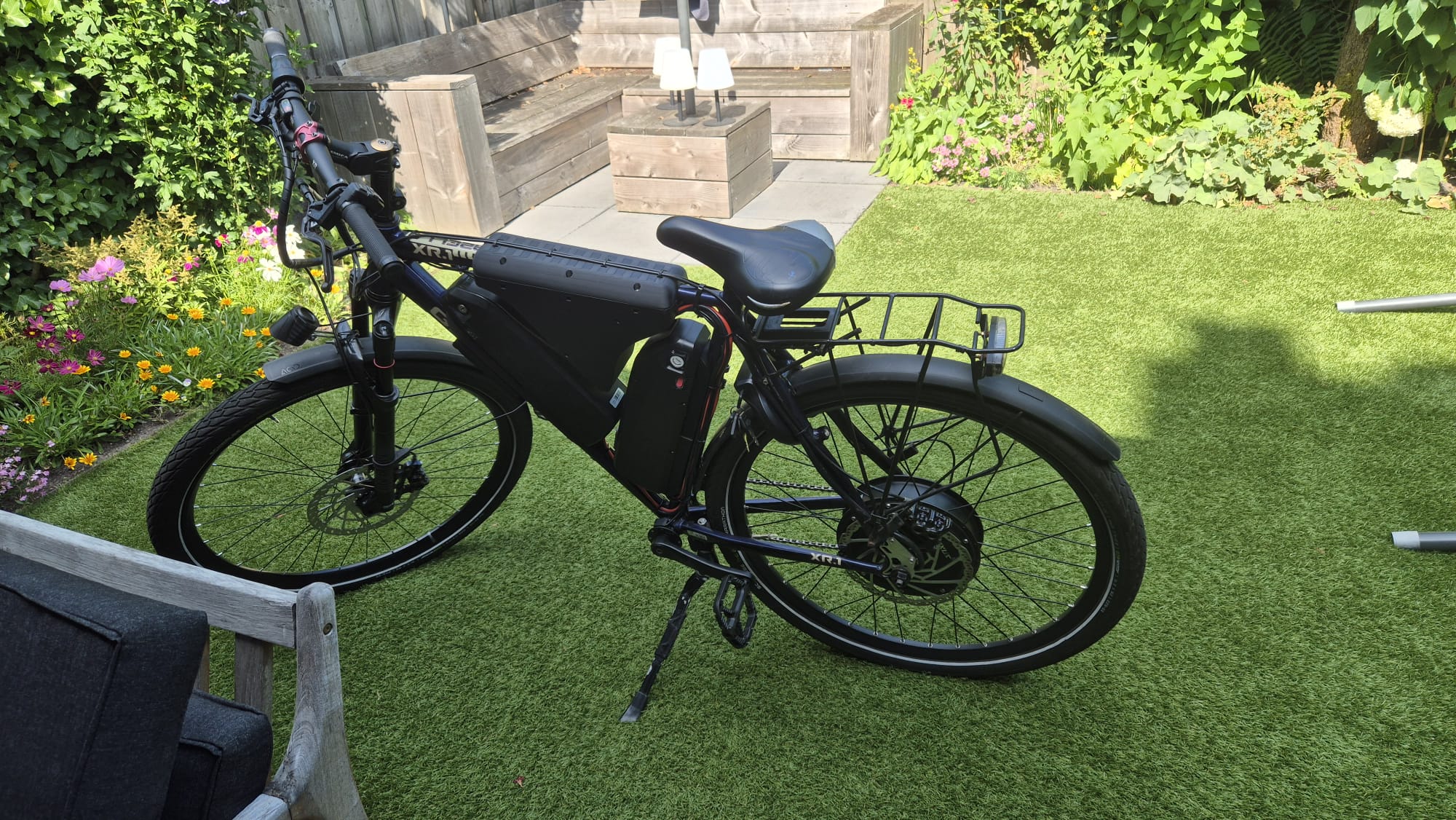
I also wanted to reposition the upper battery onto the seat tube. This would make the bicycle look less unconventional and would lower the overall centre of gravity. The available space appeared to be extremely tight. By this point, I had also learned how to use 3D scanning for several of my other projects.
I stripped my father’s matching bicycle frame and 3D scanned it. I then reverse engineered the frame geometry.
I also 3D scanned and reverse engineered the shell of the downtube batteries.
I created a complete assembly in Onshape and carefully considered the space required to remove and reinstall the batteries. After a considerable amount of design work, I found a configuration in which all of the components fitted together with only a very small amount of clearance.
Direct-drive hub motor encoder integration
To eliminate the remaining problems during the transition from sensored to sensorless FOC at high motor current, I decided to integrate an encoder directly into the hub motor.
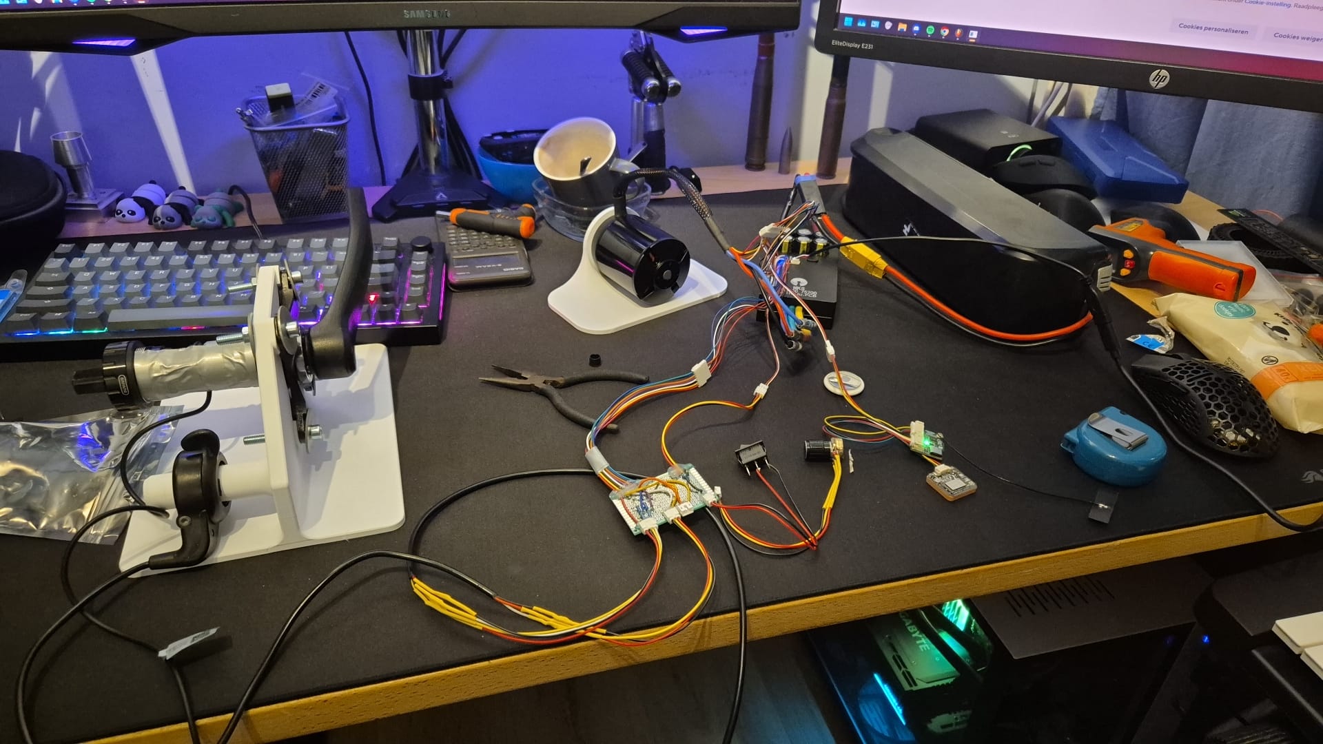
I added an RMCore controller to the VESC system. The RMCore provides multiple analogue inputs, which I used for the throttle, brake switches, power switch, and other controls. I wrote scripts for both the RMCore and the VESC so that the two controllers could communicate over CAN. This allowed the VESC to receive the control inputs from the RMCore instead of using its own analogue input pins. As a result, the analogue inputs on the VESC became available for an encoder.
The hub motor already had an additional six-core Hall sensor cable. I wanted to reuse these conductors for the encoder. This significantly limited the available encoder options. The encoder needed to be a compact ring-shaped design that could physically fit inside the direct-drive hub motor. RLS was one of the few manufacturers offering an encoder suitable for this application.
I initially purchased a conventional SinCos encoder from RLS. Its output signals had to be adapted to the 3.3 V analogue input range of the VESC. I used an AD620 instrumentation amplifier module for each signal channel. Before modifying the actual hub motor, I created a bench setup using another BLDC motor and VESC that I already had available. This allowed me to verify whether the encoder provided better low-speed position feedback than the original Hall sensors. The experiment was successful.
I then opened the hub motor and 3D scanned both the stator and the side plate. Using these scans, I checked whether an RLS Orbis encoder would physically fit inside the available space and designed the required mounting components. I ultimately selected the differential SinCos version of the RLS Orbis. The differential interface used exactly six conductors, matching the existing Hall sensor wiring. A differential signal was particularly useful because the encoder wiring runs through the same main cable as the high-current motor phase wires. Differential signalling therefore provides improved noise rejection in this electrically noisy environment. However, the VESC cannot directly read differential SinCos signals. Each channel therefore had to be converted from differential to single-ended using an AD620 instrumentation amplifier.
The AD620 modules required calibration. I created another breadboard test setup using a spare VESC and adjusted the modules to produce approximately 2.8 V peak-to-peak signals centred around 1.65 V, matching the VESC’s 3.3 V analogue input range. Once the correct potentiometer values had been determined, I recorded their resistance values. I then desoldered the potentiometers and replaced them with fixed resistors so that vibration or accidental adjustment could not change the calibration. The calibrated AD620 modules were mounted onto another 3D-printed PCB that acted as an interface between the encoder electronics and the VESC.
The RLS Orbis encoder was connected through the existing Hall sensor wiring and mounted directly inside the hub motor. The result is full closed-loop torque control from standstill, providing up to approximately 280 Nm, while the transition to sensorless control at higher speed is now extremely smooth. As far as I am aware, I may be one of the first people to integrate this type of high-resolution encoder into a direct-drive E-bike hub motor specifically for closed-loop VESC control.