Mirte MASTER-based Lab Cleanup Robot
Mirte MASTER-based autonomous laboratory cleanup robot made for the mechanical engineering bachelor graduation project.
Project Overview
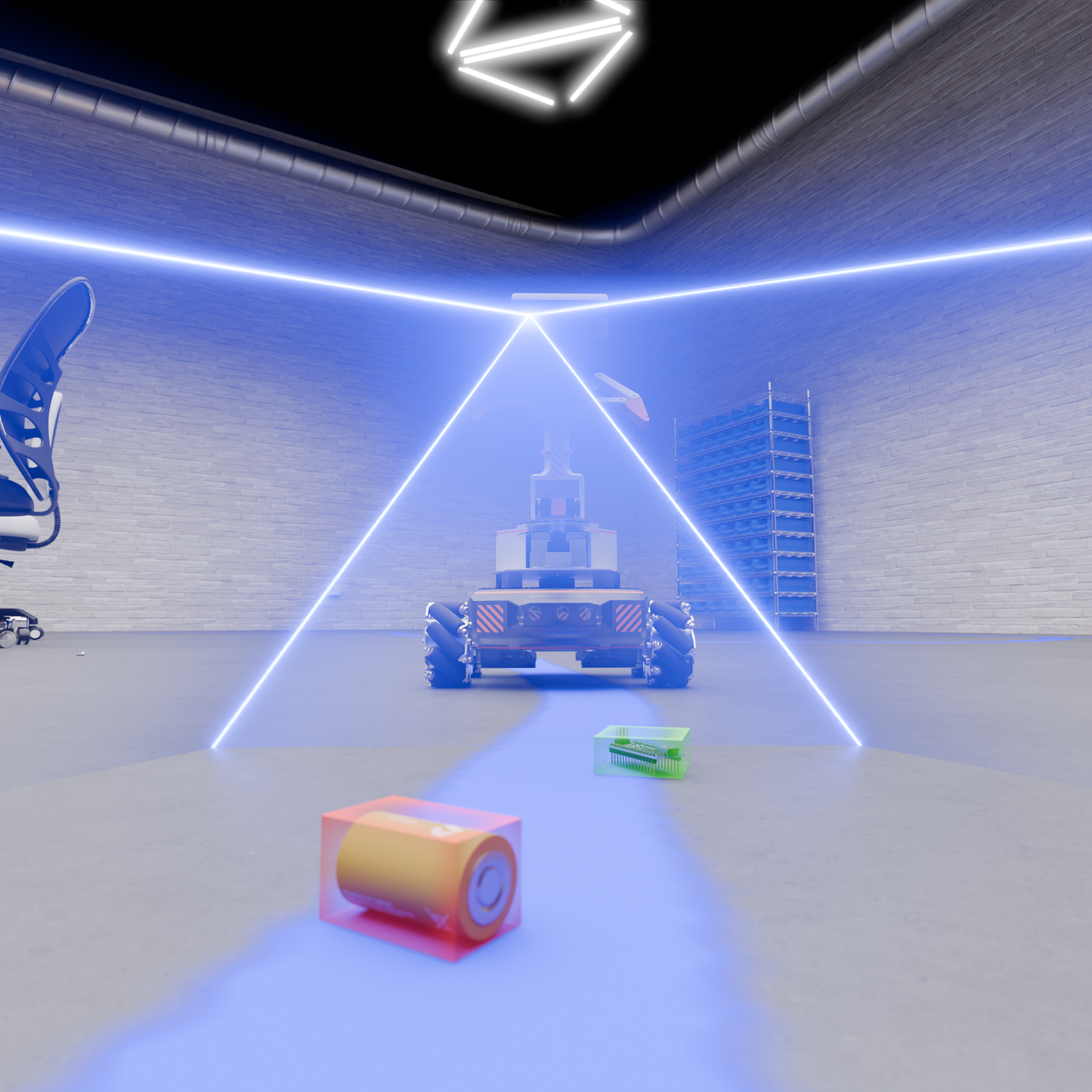
For our Bachelor’s graduation project at TU Delft, our team developed an autonomous laboratory cleanup robot based on the MIRTE Master mobile manipulation platform.
The goal was to develop a robot capable of autonomously exploring and mapping a laboratory environment,
systematically searching the accessible floor area, detecting and localising objects, picking them up using a robotic arm, and sorting them into separate waste compartments.
The resulting system combined autonomous navigation, coverage planning, 2D and 3D perception, object classification and robotic manipulation within a distributed ROS 2 architecture.
Mechanical Modifications
Although the project was based on the existing MIRTE Master V2 platform, several mechanical modifications were required to make it suitable for autonomous laboratory cleanup.
Chassis
The original MIRTE Master used clear PMMA plates for parts of the chassis. Early testing showed that these plates could fracture when subjected to mechanical loading. The PMMA top and bottom plates were therefore replaced with 1.5 mm aluminium plates. Aluminium provided similar structural functionality while being substantially less brittle. The side panels were 3D printed using translucent PETG. This retained visibility of the electronics status LEDs while also providing a tougher and more impact-resistant chassis. Two separate waste compartments were integrated into the robot to allow collected objects to be sorted into different categories.
Gripper
The standard MIRTE Master gripper was also modified to improve reliability when handling small laboratory objects. The gripping surfaces were covered with soft 83A TPE and an additional rubber anti-slip coating. This increased friction between the gripper and smooth plastic objects and improved grasping performance when objects were approached at non-ideal angles.
RGB-D Camera Position
Initial testing showed that the original low-mounted RGB-D camera position produced insufficient depth information for reliable object localisation. The camera was therefore relocated to the end of the robotic arm above the gripper. This increased the camera height and allowed its viewing angle to be adjusted, significantly improving the quality of the depth information available for the 3D perception pipeline.
Simulation and System Integration
A significant part of the software stack was initially developed and tested using Gazebo.
Simulation allowed the navigation, manipulation and high-level behaviour software to be developed before the physical robot became available.
When transitioning to the real MIRTE Master, several changes were required. Simulated clock usage was removed, navigation parameters such as the robot and inflation radii were adjusted, and sensor behaviour had to be reassessed.
The Orange Pi 3B also proved insufficient for running the entire software stack simultaneously.
Computationally intensive tasks, including parts of the cleanup and point-cloud processing pipelines, were therefore moved to an external laptop connected to the robot.
This distributed setup introduced clock-synchronisation problems between machines. Chrony was eventually introduced to synchronise the system clocks and substantially reduce TF and timestamp-related errors.
System Architecture
The robot was developed as a ROS 2-based mobile manipulation system consisting of three main subsystems:
- navigation and coverage planning;
- perception and object classification;
- robotic manipulation.
A global behaviour tree implemented using py_trees_ros coordinated these subsystems into a single autonomous cleanup sequence.
The robot first explored and mapped its environment. Once the environment was sufficiently mapped, it transitioned to systematic coverage navigation.
When an object was detected during coverage, the current navigation task was paused. The robot then approached the object, verified that it was still detectable,
picked it up, sorted it into the appropriate compartment and subsequently resumed the remaining coverage path.
This architecture allowed the navigation, perception and manipulation systems to operate as separate components while remaining coordinated through a single high-level behaviour structure.
Navigation
The navigation stack was responsible for autonomous mapping, exploration and systematic coverage of the laboratory environment.
Mapping and Frontier-Based Exploration
SLAM Toolbox was used to construct and maintain an occupancy-grid map from the robot’s 2D LiDAR data while simultaneously estimating the robot’s position within the environment.
Rather than requiring a predefined map, the robot used frontier-based exploration to autonomously discover the laboratory. Frontiers represent boundaries between known and unexplored regions of the occupancy map.
By continuously navigating toward these regions, the robot could progressively expand its map without manually specified exploration waypoints.
Once the environment was considered sufficiently explored, the behaviour tree allowed the robot to transition from mapping to its cleanup and coverage task.
Coverage Planning
After mapping, the robot needed to systematically traverse the accessible floor area to search for objects.
Multiple coverage-planning approaches were investigated. The main implemented approaches were:
- a morphology-based skeleton coverage planner;
- a grid-based spanning-tree coverage planner.
The morphology-based planner extracted the free space from the navigation costmap and skeletonised it to obtain a network of paths through the environment. A graph was constructed from this skeleton and a nearest-neighbour strategy was used to generate an ordered path between its endpoints. The spanning-tree planner instead discretised the available free space into a grid. A depth-first search was used to construct a spanning tree, after which a path was generated around the resulting tree to systematically cover the environment. The two approaches showed different strengths. The skeleton planner performed well in cluttered laboratory environments and produced relatively smooth trajectories with fewer sharp turns. The spanning-tree planner provided denser coverage in larger open areas, but generated more tight turns and was more sensitive to accumulated odometry drift.
Local Navigation
Nav2 was used for low-level navigation, costmap generation and execution of the generated coverage trajectories.
For local trajectory control, the robot used the MPPI controller. This controller continuously evaluates possible trajectories using the live navigation costmap,
allowing the robot to react to obstacles and moving people while still following the planned coverage route.
Coverage execution was designed to be interruptible. When the perception system detected an object, the active Nav2 coverage task could be paused, the remaining portion of the path retained,
and navigation resumed after the object had been handled.
Perception
The perception system was responsible for three main tasks:
- object detection;
- object classification;
- spatial localisation.
Two complementary perception pipelines were developed: a 2D RGB-based detection and classification pipeline using YOLO26, and a 3D point-cloud localisation pipeline using the RGB-D camera.
2D Object Detection and Classification
For 2D perception, a custom YOLO26 Nano model was trained using images captured with the camera included with the MIRTE Master platform.
Video recordings were collected in several different environments and individual frames were extracted to construct the training dataset. Images containing excessive motion blur were removed before annotation.
The remaining training images were manually labelled using Label Studio. A total of 1,206 bounding boxes were created across seven colour classes:
- green;
- red;
- purple;
- white;
- light-grey;
- dark-grey;
- black.
The YOLO26 Nano variant was selected because the MIRTE Master uses an Orange Pi 3B with limited onboard computing resources.
The Nano model offered a suitable compromise between detection performance and inference speed for real-time robotic operation.
The original project objective was to distinguish between electronics and non-electronics in addition to determining whether an object was graspable.
However, practical testing showed that the supplied camera suffered from motion blur, changing exposure and limited image quality.
The classification problem was therefore reduced to distinguishing between colourful and greyscale objects while retaining graspability as an important property.
The final custom YOLO26 model was able to consistently classify the objects used during testing.
3D Object Localisation
The RGB-D camera was also used to determine the three-dimensional position of objects around the robot.
Point clouds generated from the depth camera were processed using Open3D.
Large planar surfaces such as the laboratory floor were removed using RANSAC.
After removing these planes, the remaining points predominantly represented smaller objects within the environment.
These points were subsequently clustered using DBSCAN, allowing individual objects to be separated from each other.
For each detected cluster, an oriented bounding box was generated. This provided estimates of:
- object position;
- orientation;
- dimensions.
The resulting detections were transformed from the camera coordinate frame into the global map frame using the ROS 2 TF tree.
Objects overlapping occupied regions of the navigation costmap were filtered out before being passed to the rest of the system.
During testing, this pipeline was capable of localising objects approximately 1–6 cm in size.
The 3D localisation pipeline and YOLO26 classifier could operate simultaneously, combining geometric information from the depth camera with semantic information from the RGB detector.
Robotic Manipulation
Object manipulation was performed using the MIRTE Master’s 4-DOF robotic arm and MoveIt 2.
The original MIRTE Master manipulation configuration did not provide sufficient positioning accuracy for reliably grasping small objects.
Initial end-effector positioning errors were approximately 15 cm.
The motion-planning configuration was therefore reworked so that arm positioning no longer depended on approximate joint configurations.
The planning approach was adapted to the limited four degrees of freedom available on the MIRTE Master arm.
After these changes, the end-effector positioning error was reduced from approximately 15 cm to only a few millimetres.
This increased accuracy was necessary for integrating the manipulator with the object poses generated by the perception system.
Performance
The final prototype demonstrated that the MIRTE Master could support the complete hardware and software stack required for an autonomous laboratory cleanup robot. The developed perception pipeline successfully localised and classified small objects, while the manipulation improvements reduced end-effector positioning error from approximately 15 cm to only a few millimetres. The coverage-planning experiments also highlighted a clear trade-off between the implemented approaches. The morphology-based skeleton planner performed particularly well in cluttered laboratory environments and generated fewer sharp turns, helping reduce localisation drift. The spanning-tree planner produced denser coverage in open environments but resulted in more aggressive turns and greater accumulated odometry error. Together, the navigation, perception and manipulation systems demonstrated the feasibility of using the MIRTE Master as an autonomous mobile manipulation platform for laboratory cleanup.
Graduation Project Documentation
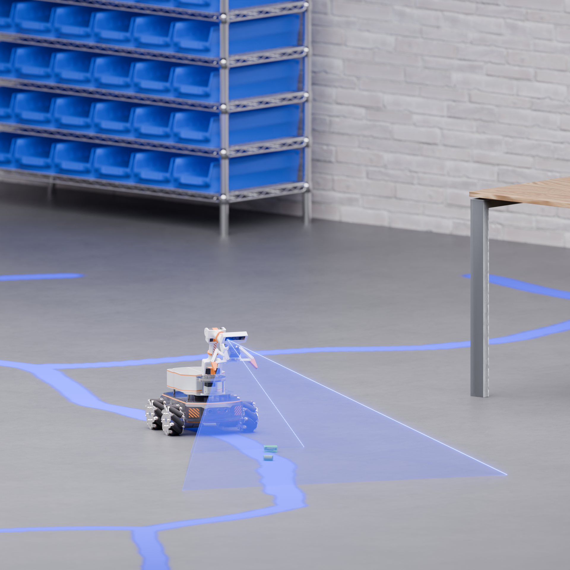
Full project documentation, including system architecture, methodology, experiments, results and PDF-download of the report.
MIRTE Master Documentation
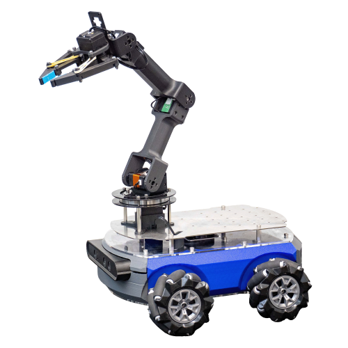
Official documentation for the MIRTE Master robotic platform used as the basis for this project.
Interactive CAD Model
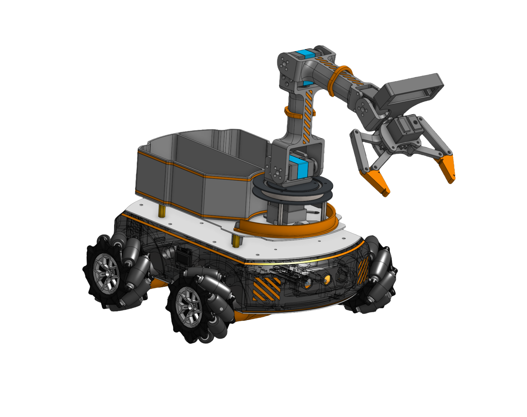
View the complete modified MIRTE Master assembly and mechanical design in Onshape.