Railgun
A functional railgun built for the VWO graduation project.
Backstory
I’ve been intrigued by machines that launch projectiles from an early age. My passion started in my childhood with crafting simple bows and arrows, which quickly evolved into building crossbows and spring-loaded contraptions. Over time, my projects grew more complex, moving from aerosol cannons and pneumatic systems to ultimately designing a railgun. The railgun worked by simultaneously forcing a high current and a strong magnetic field onto a projectile to create a large Lorentz force, propelling the projectile forward. The high-current source consisted of two parallel heavy-duty capacitors that were charged up to 400v.
Technical Specifications & Components
The railgun system consisted of two major components: the railgun body and the high-current power source.
The railgun consisted of the following components:
- Stacked hardwood multiplex
- Two steel “rails”
- Clamping hardware
- PVC pipe
- String
The high-current power source consisted of:
- 2x Kemet ALS70A163QS450 capacitors (450v, 16000µF, ripple current: 36.2A, ESR @100hz: 16 mΩ)
- DC-DC high-voltage booster.
- Mounting hardware for connecting everything
- Rigid plastic enclosure
- Old laptop charger
- 2x 4/0 (0000) AWG wire
Design & Challenges
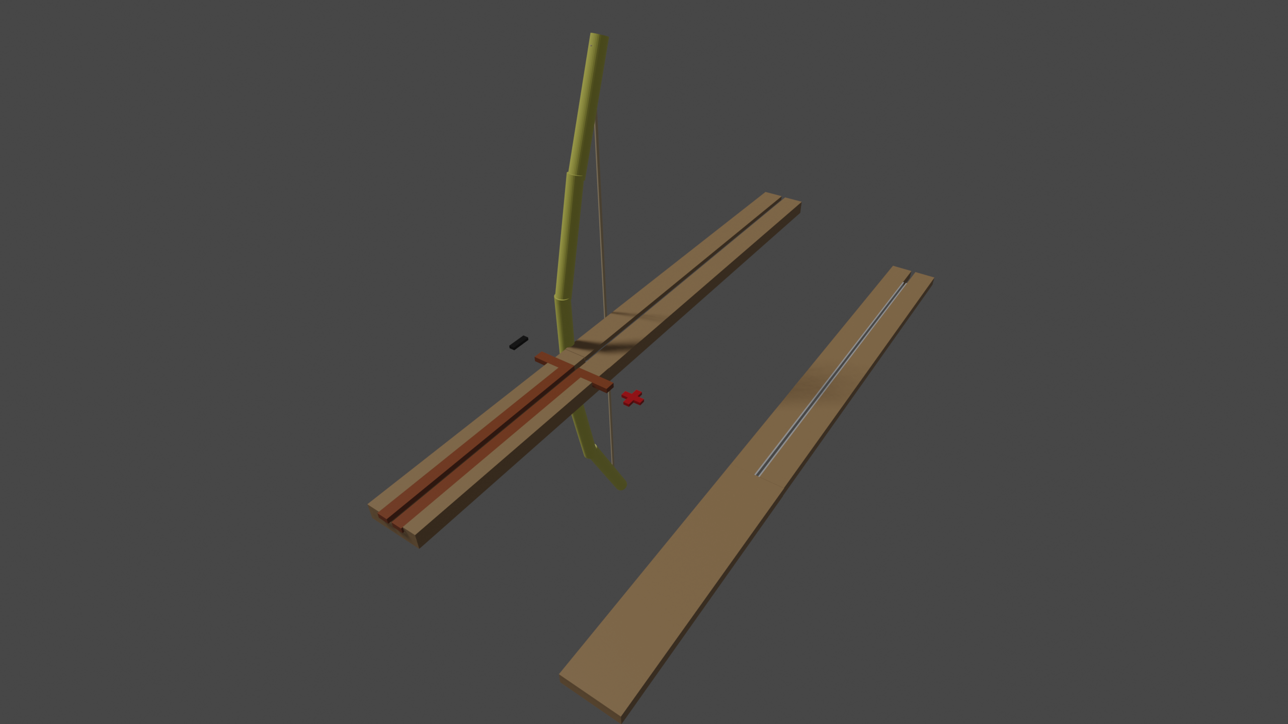
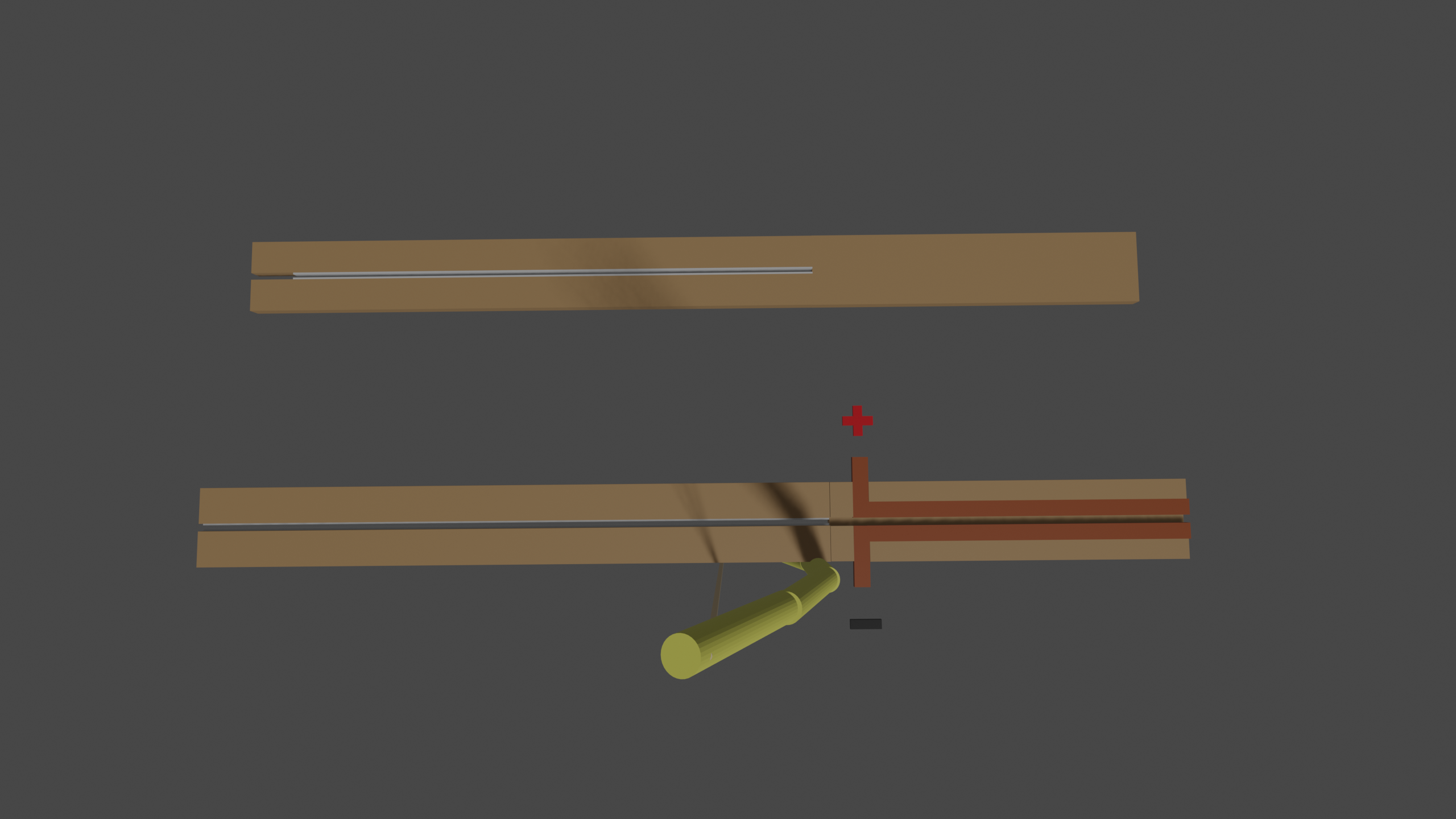
The railgun was constructed by layering thick pieces of hardwood multiplex on top of eachother clamped by large nuts and bolts, with some space in the middle layer for the two steel rails. The rails where tightly clamped down by keeping them slightly taller than the layer which they where placed in, resulting in them being clamped down firmly. On the starting end of the rails, heavy gauge wires were connected to the high-current powersource.
Injection Mechanism
A key aspect of making a functioning railgun is that the projectile already needs to be in motion once it completes its circuit with the “rails” otherwise the inmmense heat welds the projectile itself in place. To overcome this, a crossbow-like contraption was placed at the breech of the railgun to launch the projectile at speed into the railgun element. For safety while testing, the crossbow could be triggered at distance by a pin with a long pull-string.
Projectile Design
The projectiles were made by cutting a metal plate in “strips” and folding them into a v-shape. This way the projectile would be able to make good contact by unsing the v-shape as a spring against the two rails, ensuring good electrical contact. However, too much pressure on the contacts, and the projectile would weld itself to the rails.
High-current powersource
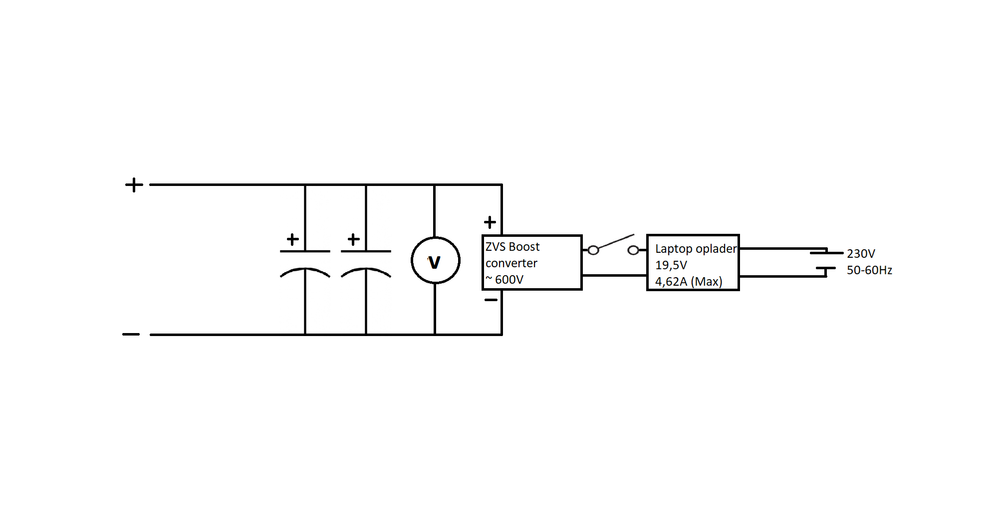
The high-current source was made by using two large capacitors connected in parallel using metal busbars. This capacitor bank was charged by a DC-DC high-voltage booster connected to an old laptop charger. Also a voltage reader was connected to the bank for charging to a specific voltage. In the early stages of the project the controlling of the charged voltage was done by turning the laptop charger on and off. Later this was automated by using an arduino, a voltage divider and relays to prevent self-discharge of the capacitors during experiments.
Results
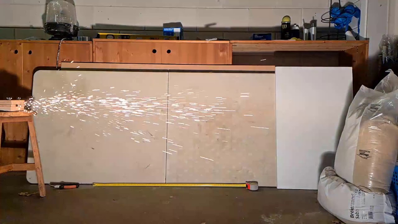
In the end we ended up firing quite a large amount of projectiles without the railgun needing maintenance. The railgun, at times, managed to puncture the sandbag that we used as target. A video of a railgunshot can be seen below.
Old Report
The old report can be seen below.