SLIP
A multidisciplinary project in which a custom high-power unmanned ground vehicle was designed and built for heavy payloads, harsh terrain and autonomous robotics research. Developed at RoBoHouse Delft in collaboration with SUSAG.
Project description
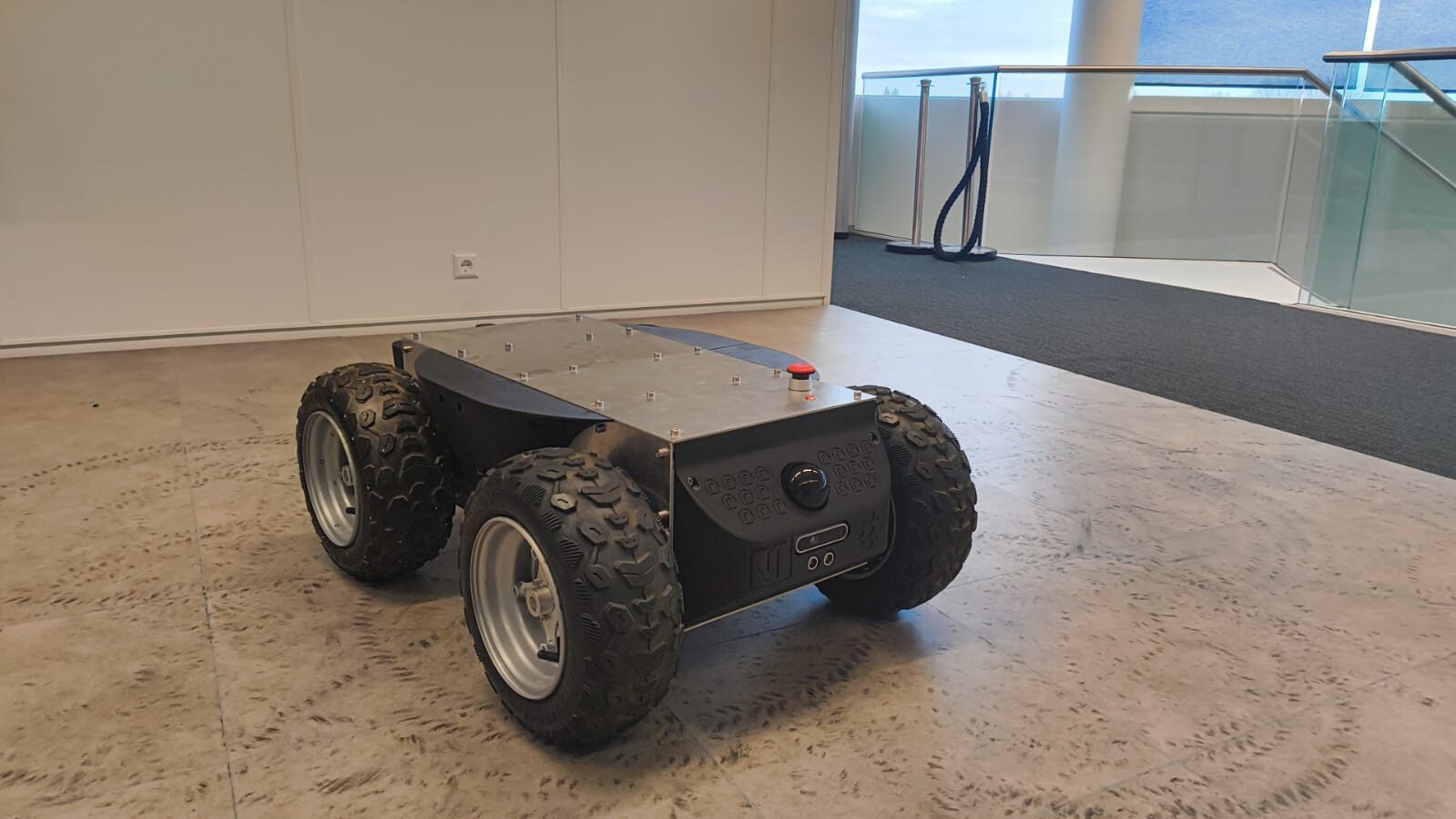
SLIP — Scalable Locomotion for Imperfect Places — is a powerful skid-steer unmanned ground vehicle developed as a platform for autonomous navigation and robotics research. I worked on the project as the Lead Mechanical Engineer, taking responsibility for the design and integration of the physical platform. Although my primary responsibility was mechanical engineering, I also assembled and integrated the electrical system of the vehicle. My personal engineering goal was to develop a UGV that could be manufactured relatively inexpensively while offering substantially more drivetrain capability than commercially available research platforms in the same size class, using the Clearpath Husky A300 as a reference point. The resulting platform combines a custom high-capacity battery system, four independently driven wheels, high-torque BLDC drivetrains, onboard computing and a multi-sensor perception system in a compact modular chassis.
My contribution
I worked on the SLIP project as the Lead Mechanical Engineer, while a colleague focused on the robotics and autonomy stack. My responsibility was the development and integration of the physical vehicle. This included the mechanical architecture, component layout, drivetrain integration, structural design, packaging, and ensuring that the platform could accommodate the sensing, computing, and electrical hardware required by the robotics system. In addition to the mechanical work, I also assembled and integrated the electrical system of the vehicle. This involved combining the power distribution, motor controllers, onboard computing, sensors, and supporting electronics into the mechanical platform. Because the mechanical and robotics systems were developed in parallel, close coordination was important. Sensor placement, electronics packaging, accessibility, wiring, cooling, and drivetrain behaviour all created constraints that had to be considered in the mechanical design. This made my role primarily focused on mechanical system design and physical integration, while ensuring that the vehicle provided a reliable platform for the robotics functionality developed by the rest of the team.
Mechanical architecture
The vehicle was built around a central frame constructed from 30 × 30 mm aluminium profiles, with an independently driven wheel module mounted at each corner. The frame architecture was deliberately kept modular. Rather than designing the chassis as a single welded structure, the aluminium profile construction made it easier to reposition components, modify the platform and access internal hardware during development. At the centre of the chassis sits a custom 41.6 V, 50 Ah LiFePO4 battery pack, around which the drivetrain, computing hardware, sensors and electronics were packaged. The exterior of the frame was enclosed using 3 mm aluminium panels combined with custom 3D-printed panels for mounting sensors, switches and other hardware.
High-torque drive units
Each corner of the vehicle contains an independent drive unit designed specifically for high torque at low speed. Each wheel can deliver approximately 120 Nm of torque.
A drive unit consists of:
- Flipsky 7070 110KV BLDC motor
- ODrive S1 motor controller
- 20:1 NEMA 23 planetary gearbox
- 2× 6813-2RS bearings
- 14 mm keyed flange coupler
- custom aluminium transfer plate
- custom stainless-steel mounting plates
- 16×8.00-7 ATV wheel
- Tuvot 125/60-7 off-road tyre
- brake resistor
- custom 3D-printed components
- mounting hardware
Wheel-integrated gearbox
One of the main packaging challenges was fitting four high-torque drivetrains inside a relatively compact platform. To reduce the amount of drivetrain hardware occupying the inside of the chassis, I integrated the gearbox into the wheel itself. The planetary gearbox was disassembled and incorporated into a custom wheel assembly. A 3D-printed sleeve was fitted around the gearbox housing, onto which two large bearings were mounted. A custom inner wheel cup then rotated around these bearings. This allowed the gearbox housing to serve a second function as the wheel axle, reducing the packaging volume required by the drivetrain. The inner wheel cup also significantly increased the structural rigidity of the wheel assembly. This was important because the platform was intended to support additional equipment and experimental setups on top of the robot. The gearbox was mounted to three custom stainless-steel plates, which also supported the BLDC motor and motor controller inside the chassis. These plates were then mounted directly to the aluminium frame to provide a rigid structural connection between the drivetrain and the chassis.
Motor control and odometry
Each wheel is controlled by an ODrive S1. The ODrive was selected partly because its absolute magnetic encoder provides direct wheel-position feedback. This made the drivetrain suitable for wheel odometry while also allowing the motor to produce controlled torque from standstill. Communication between the four ODrives and the onboard computer is handled over CAN bus, connected to the computer through a USB-to-CAN interface. Regenerative braking feeds energy back into the main battery pack. Because the amount of regenerative current that can safely be accepted by the battery is limited by the BMS, each ODrive was also equipped with a brake resistor. When the permitted regenerative current is exceeded, excess energy can instead be dissipated through these resistors.
Battery and power system
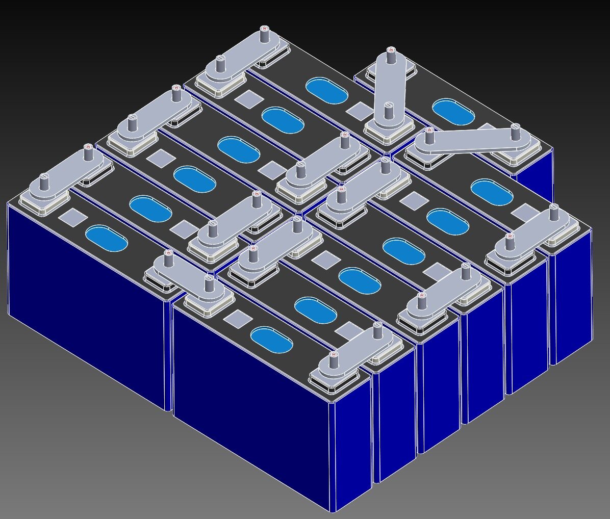
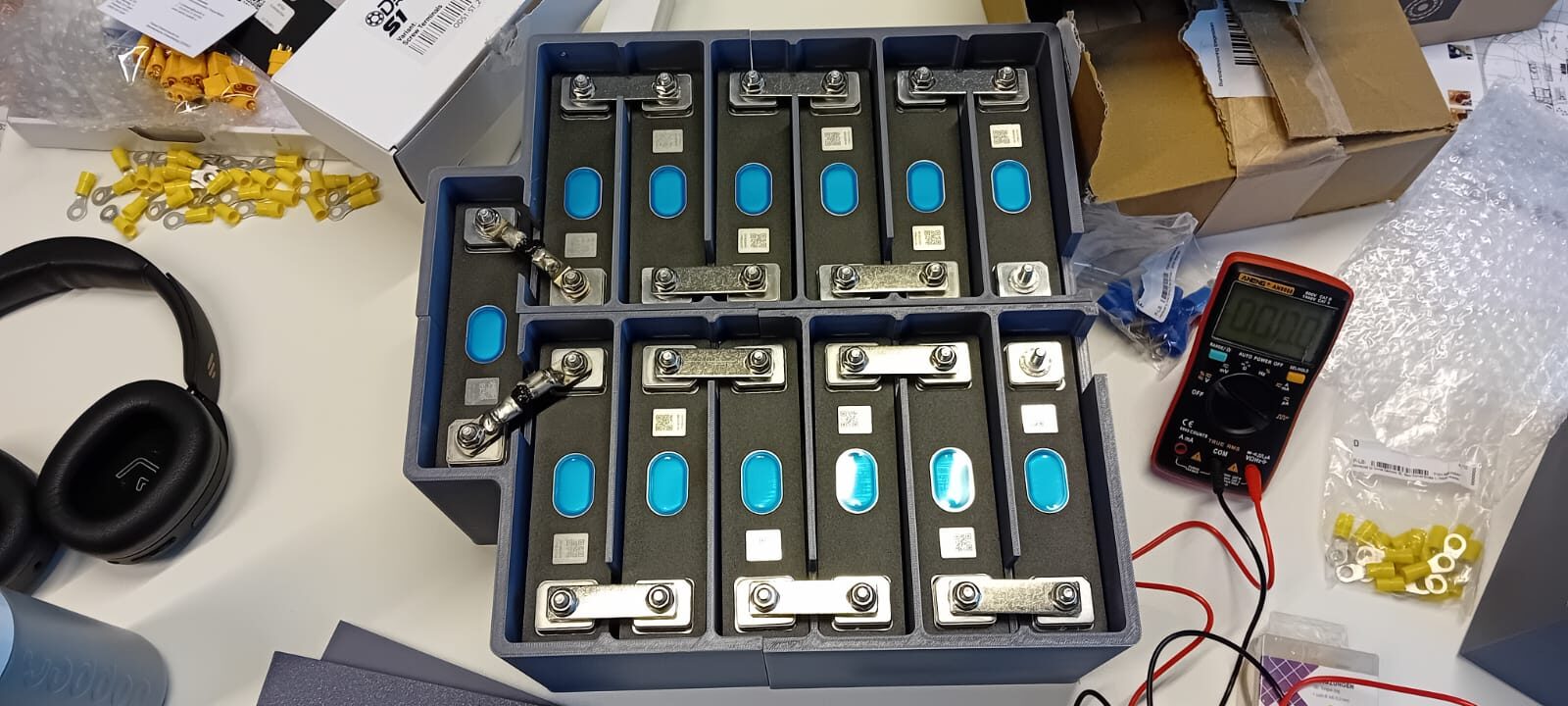
The SLIP platform was designed around a custom 41.6 V, 50 Ah LiFePO4 battery pack.
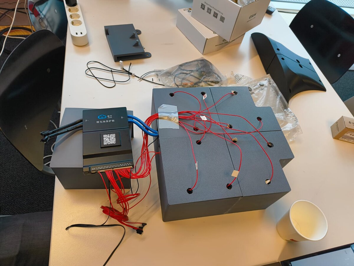
The battery consists of:
- 13S configuration
- REPT CB3914895EA 50 Ah prismatic LiFePO4 cells
- JK BD6A20S10PR 100 A smart active-balancing BMS
- busbar cell interconnections
- custom 3D-printed PETG cell enclosure
- Littelfuse DCNEV250-G 250A high-current relay
The battery enclosure was designed specifically around the prismatic cells and integrated into the centre of the chassis. A high-current relay provides a hardware-level method of disconnecting the drivetrain from the battery. The emergency stop on the top panel directly controls this relay, providing a physical shutdown mechanism independent of the onboard computer.
Electrical and computing integration
Although my main role within the team was mechanical engineering, I also assembled and integrated the electrical system of the vehicle. The main onboard computer is an NVIDIA Jetson Orin Nano, which handles communication with the drivetrain and provides computing resources for the robotics system. A heavy-duty 60 V to 12 V DC-DC converter supplies the low-voltage electronics from the main traction battery. The Jetson communicates with the four ODrive controllers over CAN through a USB-to-CAN adapter. The computing hardware, converters and supporting electronics were mounted directly to the frame using custom 3D-printed brackets. Designing the mechanical and electrical layouts together was particularly important because wiring access, cooling, serviceability and sensor placement all competed for the limited internal space.
Sensor integration
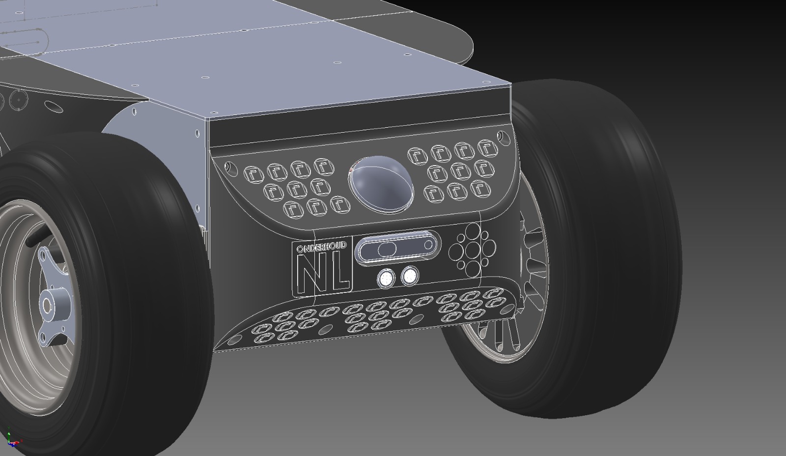
The exterior panels were designed not only as protective covers, but also as mounting structures for the robot’s sensors and controls. Ultrasonic sensors were installed on all four sides of the platform as a redundant short-range sensing system, particularly for detecting objects that may be difficult for optical sensors to perceive reliably. The rear panel contains a 2D LiDAR, while the front of the vehicle carries a RoboSense Airy hemispherical LiDAR. The RoboSense sensor was mounted at approximately 45 degrees toward the ground. This orientation allowed a single sensor to observe the terrain directly in front of the robot, the surrounding environment and parts of the ceiling, providing useful geometry for SLAM. The sensor also contains an accurate IMU that could be incorporated into the robot’s sensor-fusion system.
LiDAR thermal management
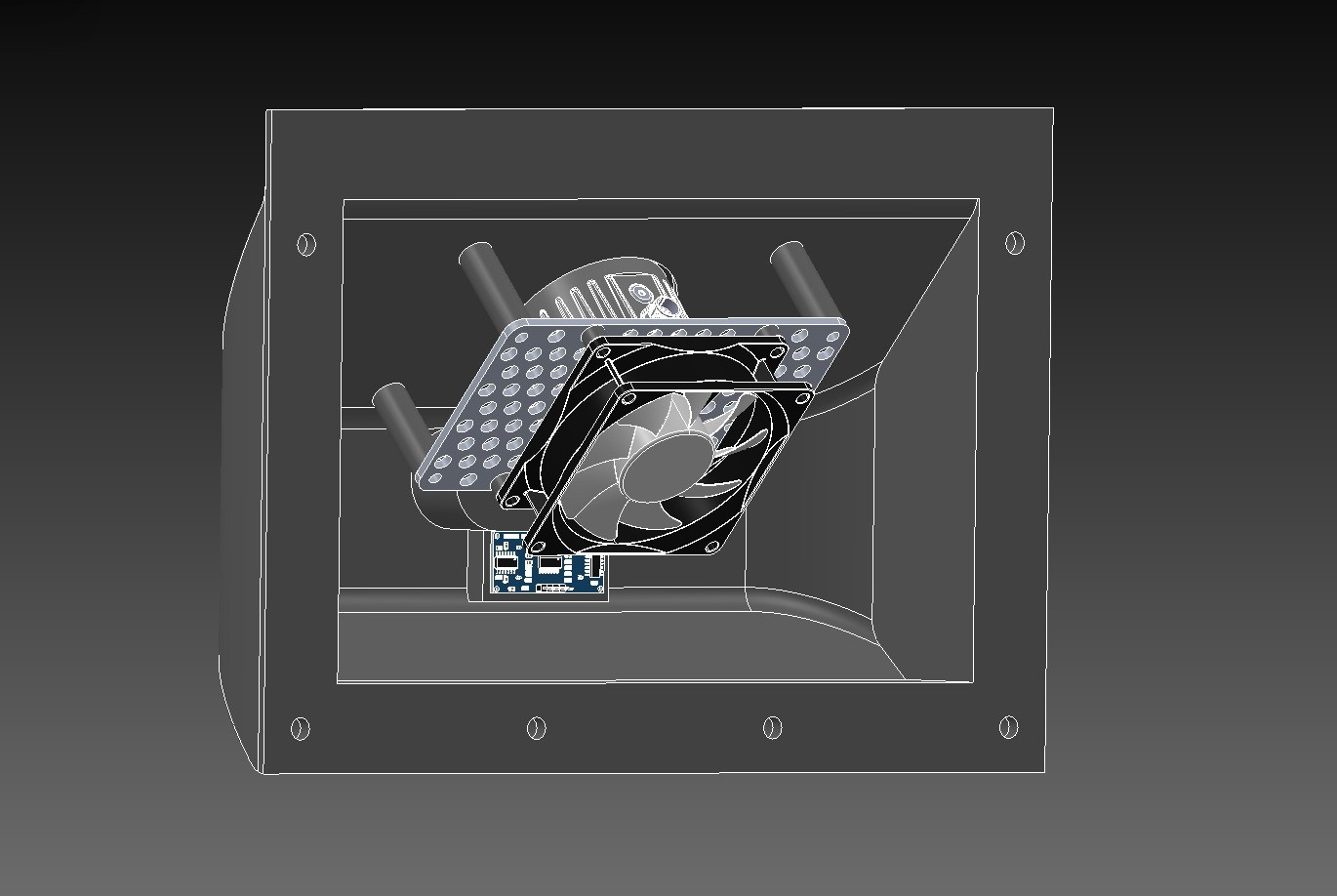
During testing, the RoboSense LiDAR became unexpectedly hot, reaching temperatures above 80 °C. Rather than accepting this as a limitation of the sensor installation, I developed a dedicated cooling solution. The LiDAR was thermally coupled to aluminium plates using thermal pads. A fan then forced air across the aluminium structure, effectively turning the sensor mount into a heatsink. This reduced the operating temperature from over 80 °C to approximately 35 °C.
Engineering approach
The project was developed within a very short timeframe and under a limited budget. Because there was little room for major redesigns or failed manufacturing iterations, many engineering decisions had to be made carefully before components were ordered or manufactured. This made simplicity, modularity and the use of readily available components important design priorities. Wherever possible, standard components and off-the-shelf hardware were combined with custom parts only where they provided a clear advantage in packaging, strength or functionality. The mechanical architecture was therefore developed with a strong focus on:
- minimizing the number of unique custom parts
- keeping components accessible for assembly and maintenance
- using 3D printing for fast and inexpensive custom integration
- reusing structural components for multiple functions
- validating critical dimensions and interfaces before fabrication
Because the schedule left little room for mistakes, the design process relied heavily on CAD integration and system-level packaging before physical assembly. Once the platform was assembled, the remaining development focused on solving practical integration issues discovered during testing, such as sensor cooling, wiring, drivetrain behaviour and component accessibility.
Manufacturing and assembly
Due to the short project timeline and limited budget, most components had to work correctly on the first manufacturing attempt. This made careful CAD integration, tolerance checking and the use of readily available manufacturing methods particularly important. Not every challenge could be predicted from CAD. One unexpectedly difficult assembly step was fitting the ATV tyres onto the rims. I initially attempted to mount them myself and successfully fitted the first tyre. The second tyre, however, required enough force to permanently deform the rim, even after lubricating both the tyre bead and rim. As a result, a replacement rim and tyre had to be ordered. To avoid damaging another wheel, I had the remaining tyres professionally mounted by a local automotive workshop. Although relatively minor compared with the drivetrain design itself, this was a useful reminder that seemingly straightforward assembly operations can introduce significant practical risks that are difficult to identify during digital design.
Performance and testing
At the nominal battery voltage of 41.6 V, each ODrive S1 could deliver approximately 1.66 kW of continuous power to its wheel, resulting in a combined drivetrain power of approximately 6.6 kW across all four wheels. The vehicle reached a measured top speed of approximately 3.6 m/s. Low-speed traction was one of the main strengths of the platform. During testing, the robot was able to push two adults who were actively resisting its motion. This was demonstrated publicly at an exhibition. The drivetrain also demonstrated substantial torque under load. With approximately 80 kg of additional payload, the robot was still able to perform an in-place skid-steer rotation on a high-grip rubber-like surface. The actual drivetrain limits were not reached during the available testing period. The tests therefore primarily demonstrated that the platform had significant performance margin beyond the loads encountered during normal operation.
Result
The completed SLIP platform provided the mechanical and electrical foundation for further robotics research. After completion, the robotics engineer on the project used the vehicle as the physical platform for his thesis research on autonomous navigation and terrain-aware control. This provided an important real-world validation of the design. The platform had to remain reliable, maintainable and accessible throughout repeated experiments rather than merely function as a one-off prototype. The vehicle was subsequently tested under more demanding conditions, including construction-site environments and operation with additional payload. During the available testing period, the actual drivetrain limits were not reached. The project therefore resulted not only in a functioning UGV, but in a reusable robotics research platform capable of supporting continued development and validation of autonomous systems
Research platform validation
A key validation of the design was that the platform remained in active use after the mechanical development phase. It was used by the robotics engineer on the project as the physical platform for subsequent thesis research. This provided a form of real-world validation of the mechanical architecture, drivetrain, power system and sensor integration, since the robot had to remain functional and maintainable throughout repeated autonomous testing.
SLIP — Autonomous Construction Robot
Project website documenting the development and testing of SLIP, an autonomous mobile robotic platform designed for construction-site research.