Mason
A jointing robot that was made in collaboration with SMB-Geveltechniek as part of the Robotics Minor of TU Delft.
Project description
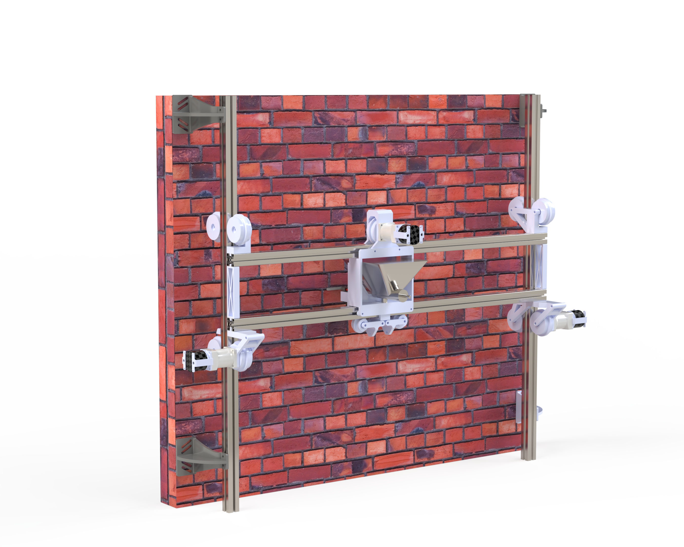
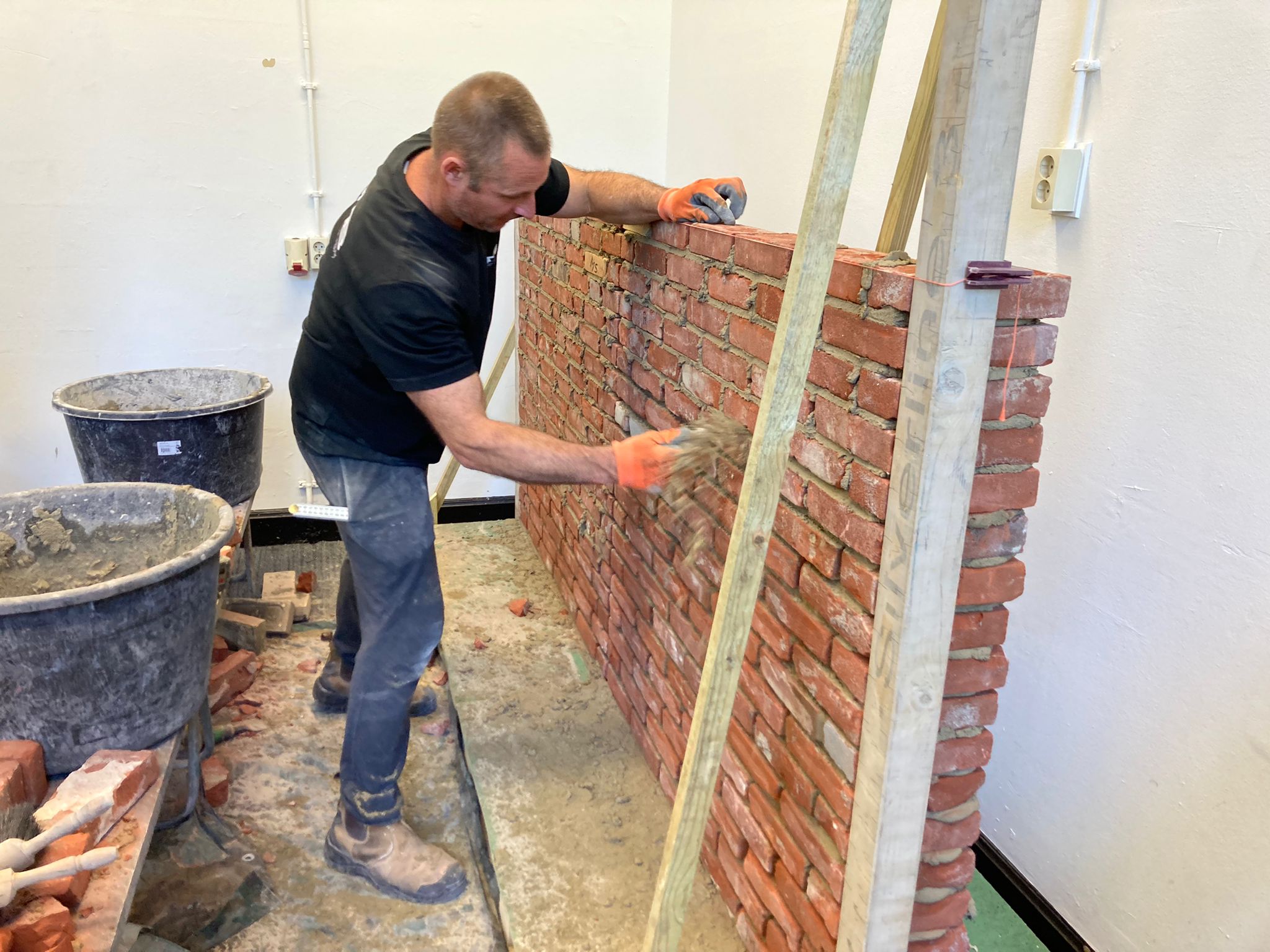
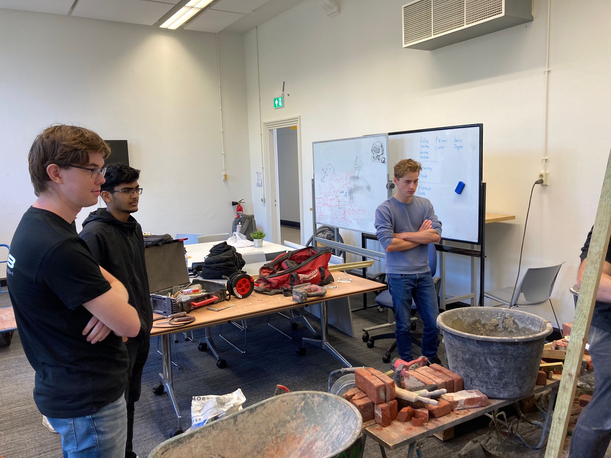
Mason was a robotic jointing system developed in collaboration with SMB Geveltechniek as part of the TU Delft Robotics Minor. The project started with several meetings with the client to understand the jointing process, the intended use of the robot and the requirements for the prototype. SMB Geveltechniek also introduced us to the practical process of constructing and finishing a brick wall, including both bricklaying and jointing. This provided important context for translating a largely manual construction process into a robotic system. The objective was to develop a robot capable of moving across a brick wall and automating several parts of the jointing process, including mortar application, smoothing and cleaning. The multidisciplinary team consisted of three mechanical engineers, two software engineers and one electrical engineer.
Project process
The project was divided across two academic quarters. During the first quarter, the focus was primarily on understanding the problem, communicating with the client and developing the system architecture. Different concepts were explored for wall mounting, movement, tooling, sensing and mortar application before the detailed mechanical, electrical and software designs were developed. During the second quarter, the emphasis shifted towards fabrication and integration. The individual mechanical, electrical and software subsystems were manufactured and assembled into a functioning prototype. Much of this phase consisted of practical troubleshooting and iterative redesign as assumptions made during CAD development were tested on the physical system. The project concluded with an integrated prototype and final demonstration to the client.
My contribution
I worked on the project as one of the three Mechanical Engineers, with primary responsibility for the design and development of the complete gantry and movement system. This included the structural layout of the gantry, the horizontal and vertical movement mechanisms, drivetrain integration and the custom components required to guide and support the moving sections. I also worked closely with the electrical engineer on the BLDC drive system, integrating the motors, encoders and VESC-based motor controllers with the mechanical drivetrain. The selected system used Flipsky 6354 140 KV BLDC motors combined with FSESC 6.7 VESC’s, 20:1 NEMA 23 planetary gearboxes and AS5047P magnetic encoders for closed-loop position control. A major part of my work therefore involved the interface between mechanical and electrical engineering rather than only the mechanical structure itself.
Gantry design
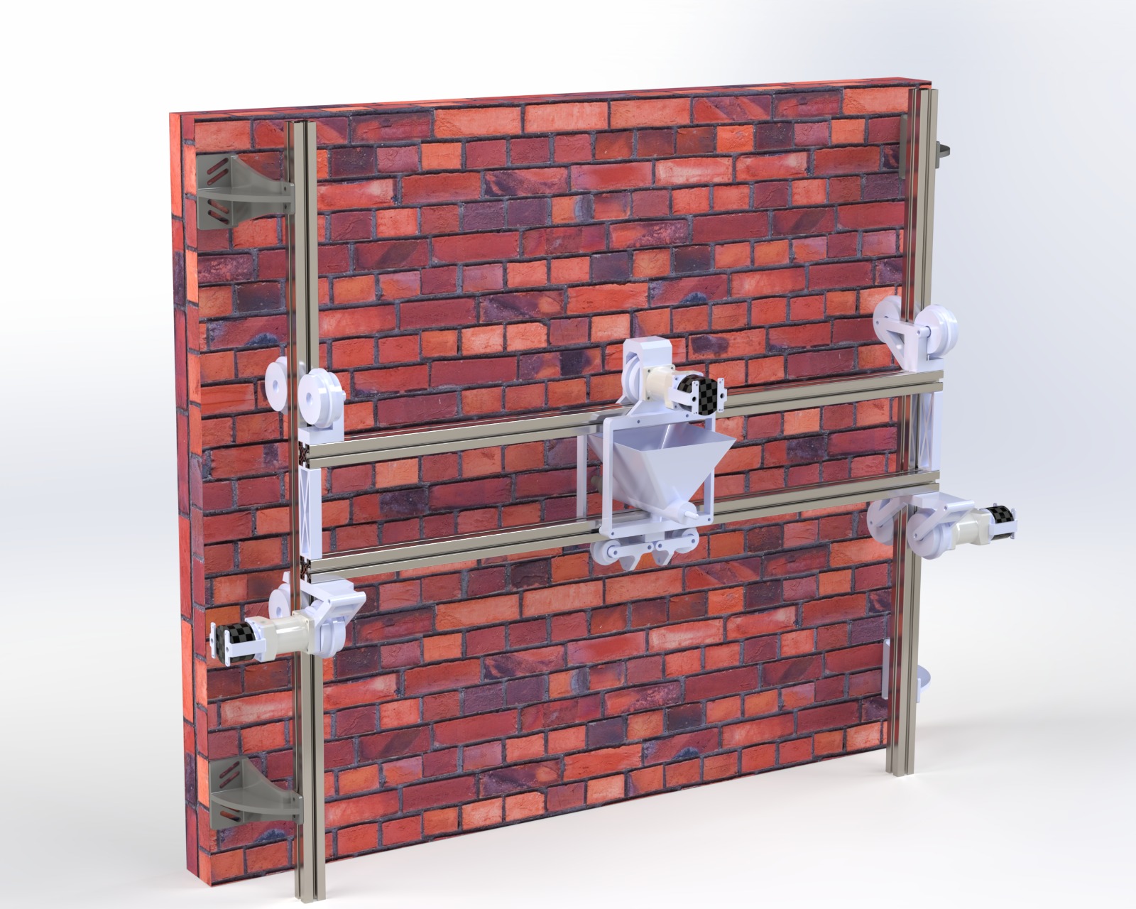
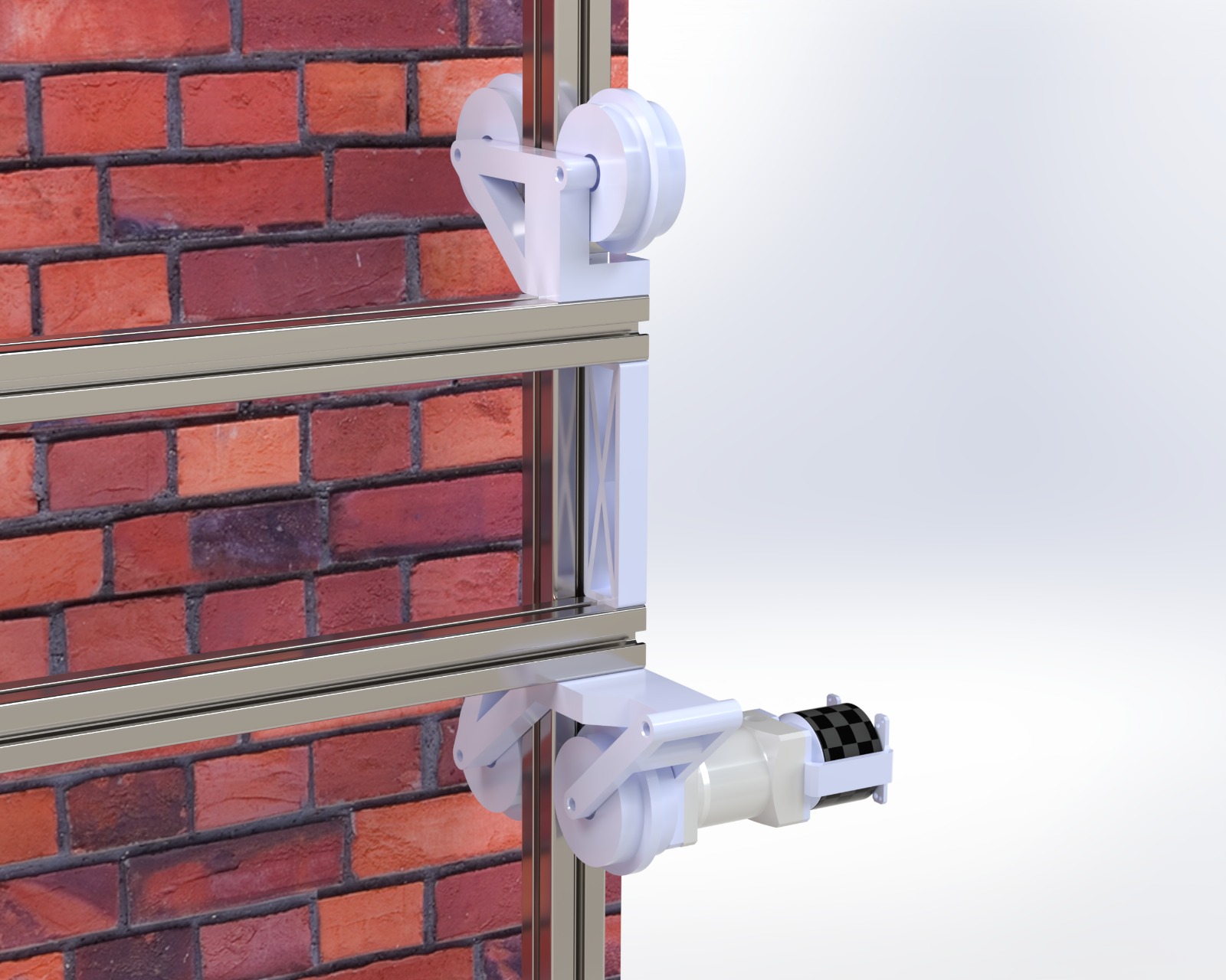
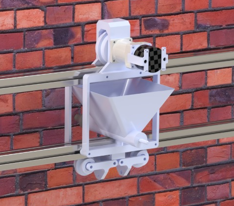
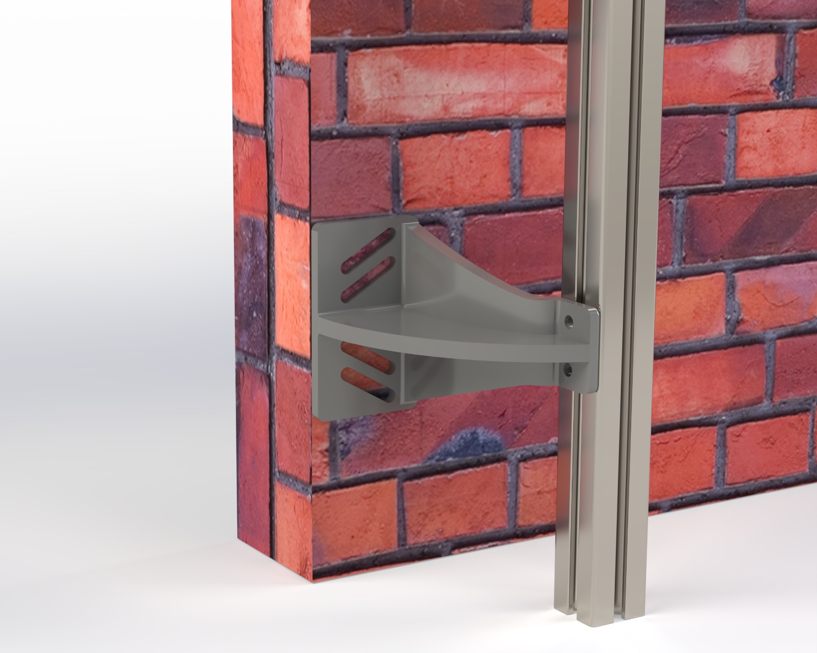
The gantry was designed as a modular frame built from aluminium profiles. The system provided independent horizontal and vertical movement while supporting the complete toolhead. A key design objective was to make the gantry easy to extend. Instead of using conventional linear rails, belts or rack-and-pinion systems, the original concept used friction-driven wheels running directly along the aluminium profiles. The driven wheels and running surfaces used rubber to generate sufficient traction. This architecture had an important advantage: additional aluminium profile sections could simply be added to increase the working area without needing to extend a belt, leadscrew or precisely align gear teeth. The horizontal and vertical movement systems used spring-loaded wheel arrangements to maintain contact with the extrusion and constrain unwanted movement. In the vertical mechanism, the geometry also used the weight of the horizontal gantry to increase the normal force on the driven wheel.
BLDC drive system
The gantry was driven using Flipsky 6354 140 KV BLDC motors combined with 20:1 planetary gearboxes to provide the required torque for moving the toolhead and lifting the horizontal gantry section. Magnetic encoders were used for closed-loop position feedback. The original design used VESC-based motor controllers, which had been selected because they offered configurable BLDC control at relatively low cost. During integration, however, the VESC-based control architecture proved less suitable for the gantry than expected. In particular, the CAN-based communication and position-control setup did not provide the reliability and behaviour we wanted for a multi-axis positioning system. The drive system was therefore changed late in the project to ODrive S1 motor controllers, which were also commanded over CAN. The ODrive controllers provided a more suitable platform for closed-loop motion control and allowed the BLDC motors to be treated more like servo axes within the gantry system. This change required additional mechanical and electrical integration work at a relatively late stage of the project, but resulted in a more appropriate drive architecture for accurate horizontal and vertical positioning.
Revisions
Late-stage drivetrain redesign
Two important limitations only became apparent during final integration.
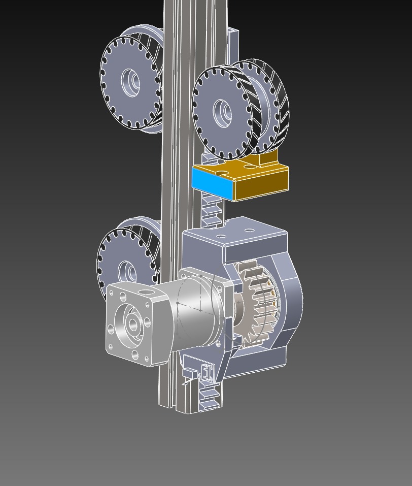
The first was mechanical. The original movement system relied on rubber-coated wheels running against rubber-coated aluminium profiles. This made the gantry extremely easy to extend because there were no belts, leadscrews or gear teeth that had to remain aligned between profile sections. During operation, however, vibration caused small amounts of wheel slip. Although the displacement per event was very small, it accumulated and affected the positioning accuracy of the vertical axes. The vertical drives were therefore redesigned to use 3D-printed rack-and-pinion transmissions. The racks consisted of stackable sections that could be added along the extrusion while retaining the modular nature of the gantry. Cutting guides were incorporated into the rack segments so that the final section could easily be shortened to match the required gantry length. The second limitation was in the motor-control architecture. The original VESC-based solution was capable of closed-loop BLDC control, but its CAN communication and control behaviour proved less suitable for the type of coordinated positioning required by the gantry. The motor controllers were therefore replaced with ODrive S1s, while retaining CAN communication between the drives and the main controller. Together, these changes transformed the movement system from the original friction-driven, VESC-controlled concept into a more deterministic rack-driven, ODrive-controlled positioning system.
Mortar extrusion redesign
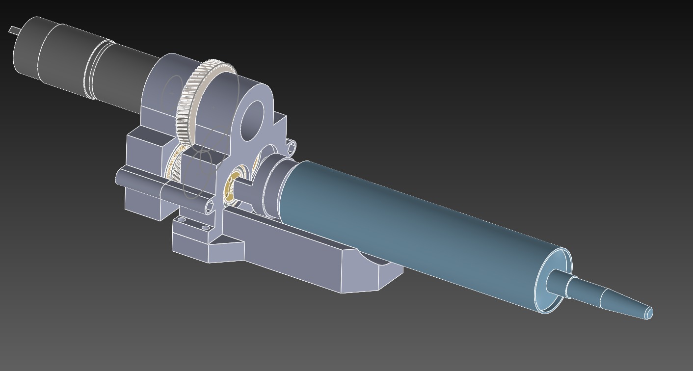
A second major issue emerged during the final stages of integration. The original design assumed that conventional jointing mortar could be extruded through the robotic tooling. In practice, the material proved significantly more difficult to transport and dispense reliably than expected. Because there was little development time remaining, the team switched to pre-packaged repair mortar cartridges, which provided much more predictable extrusion behaviour. This required a completely new extrusion mechanism. Using components that were already available in RoboHouse, I designed and built a new actuator in a very short development cycle. The mechanism used a single electric motor driving two leadscrews through a geared transmission. The two leadscrews moved a plunger forward, applying an even force to the mortar cartridge and forcing the material through the nozzle. The system was deliberately designed around available components so that it could be manufactured, assembled and tested within the remaining project time. For me, this was one of the clearest examples in the project of the difference between designing a mechanism in CAD and developing a system that must actually work under a deadline.
Engineering under time pressure
The later stages of Mason involved considerably more than simply manufacturing the original CAD model. Both the vertical drivetrain and mortar extrusion system required substantial changes after physical testing exposed limitations that were difficult to predict during the initial design phase. Instead of treating these failures as reasons to restart the design, I focused on finding modifications that could be integrated into the existing architecture with minimal impact on the rest of the robot. The rack-and-pinion conversion retained the modular aluminium gantry, while the replacement mortar extruder reused readily available components and could be manufactured within the remaining project time. These iterations became an important part of the project: designing around real-world behaviour, available hardware and a fixed deadline rather than only optimizing the initial concept.
Result
The project resulted in a functioning integrated prototype combining a modular gantry, closed-loop BLDC drivetrain, robotic tooling, sensing and software into a single system. My main contribution was the development of the gantry and its drivetrain, from the initial friction-driven concept through to the final mechanically constrained vertical drive system. I was also responsible for rapidly developing the replacement mortar extrusion mechanism when the original approach proved impractical. The project gave me practical experience with mechanical design, drivetrain development, electromechanical integration, fabrication and troubleshooting under time pressure, while working within a multidisciplinary robotics team.